Isn't this is the Antonio
An externally hosted image should be here but it was not working when we last tested it.
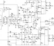
The new Crest CD3000 Class-D amp output stage
Current steering schottkys used in series with output mosfets to prevent the mosfet body diode issues during high dv/dt && di/dt..
Current sensing is done on both upper and lower rails of mosfet half bridge.....
High Side features a p-channel mosfet to prevent the failure of IR2110 in case of negative transients and also in case of mosfet failure...
Attachments
How do you come by to have the schematics??
They have changed their page so that you need a password now to download schematics 🙁 ...... but quite understandable 😀
What are the output devices .... kant make it out in this resolution ..... APT50 ..... something?
They have changed their page so that you need a password now to download schematics 🙁 ...... but quite understandable 😀
What are the output devices .... kant make it out in this resolution ..... APT50 ..... something?
Baldin said:Wow ... thats a big MosFet .... and fast too 😎 😎 😎 😎 😎
Must get me some of those😉
APT is now Microsemi[its not a merger but a takeover]
Unfortunately APT parts are now very difficult to get in our region...
Meanwhile, Does any body know how to take care of Mosfet Body Diode issues apart from using Series Schottkys....
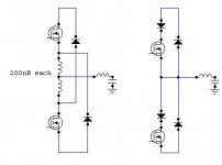
I have seen on older crest schematics, they use centre tapped inductors [200nH]in series with mosfets, in order to ADD a little offset and thus enable the additional fast recovery diode to deal with free-wheeling current...
Which one is better way.....Series Schottkys or series Inductors
imho,Which one is better way.....Series Schottkys or series Inductors
if body diode is very fast, no problem;
if body diode is causing some current peaks, coil (magnetic snubber) helps...
if body diode is big + very slow, it never should be active, so ser.+par. diodes needed
btw the APT50M65B2LL is fast, 19ns turn on, but diode is 680ns turn off !!!!!
so no way for fast switching, if diode becomes active...
I just solve your probleme in my 10Kw module. I can't give it public because I think is the biggest step done in class d for long time..Sorry for my pretention, but email me I will screen to who I can give it! I reach near 60ns rise and fall time at 450V....With simple gate drive! Only drawback, need 2 output for each leg.
Fredos
www.d-amp.com
Fredos
www.d-amp.com
Hi!
What do you mean on: "need 2 output for each leg." ? Two output for each transistor leg, or sg.?
Gyula
What do you mean on: "need 2 output for each leg." ? Two output for each transistor leg, or sg.?
Gyula

fredos said:
Hi Fredos, if it's really so, you could patent it to get decent royalty, because such technique interesting not for class D only, but in the motor control and industry at all. However, i'll afford to doubt, that it's something completely new. 🙂
Or in this state: We found a structure with any order of error correction can be realizable with Ts/2 time delay for input signal to output, so feedback may also be realizable. The simulations show working with 24 bit precision arithmetic.
Have you completed your topology?
Have you completed your topology?
Attachments
- Home
- Amplifiers
- Class D
- IR2113 blowing ! help needed...