drive them trough 10 ohm resistors or smaller.
for me it seems not that smart to use dead time before the IR chip. (extra parts)
regards,
savu
for me it seems not that smart to use dead time before the IR chip. (extra parts)
regards,
savu
Dear Sir Alex,
Could you sent me the schematic & PCB your Project please?
I'am very interested with classd amp.
My email: hari_wibowo_jmb@yahoo.com
Thankyou for your cheapness.
Hari W.
Could you sent me the schematic & PCB your Project please?
I'am very interested with classd amp.
My email: hari_wibowo_jmb@yahoo.com
Thankyou for your cheapness.
Hari W.
nice work Andrew!
Where did you get the files for DIY construction?...wish I can have it too..😀
Regards!
Where did you get the files for DIY construction?...wish I can have it too..😀
Regards!
Hi Abeteer
greetings all files can be found onthis ucd thread just stick TO orignal pcb by
egtagle THE SMALLER PCB you wont go wrong if you start your construction in a
logical way i found out the hard way see when i started this thread and when i managed
finally to make it work but better late than never check all parts before soldering and for shorts on copper side correct orientation of caps and DIODES
warm regards
andrew lebon
hi alexclaire could you please send me the schematic and pcb files with final and working class d amp vedmitraa@gmail.com
warm regards
Vedmitra sharma
warm regards
Vedmitra sharma
you won't get pcb, schematic is on my site, where you can download ithi alexclaire could you please send me the schematic and pcb files with final and working class d amp vedmitraa@gmail.com
warm regards
Vedmitra sharma
Hi Luka!
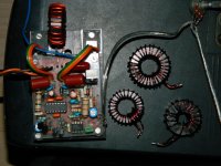
I saw your work on Elektor mains delay circuit, I built the same using the PCB lay from Elektor but I could not properly fit those bigger wirewounds so it looks like "out of nowhere" build 🙁 I wonder if you have done a modified lay-out on your PCB, the wirewounds was nicely arranged. Will you be sharing the files?
Regards!
[Sorry...I'm off topic]
I'm also sorry for off topic, but to answer.. yes, I did my own board from the begining, and the reason why everything just fitsHi Luka!
I saw your work on Elektor mains delay circuit, I built the same using the PCB lay from Elektor but I could not properly fit those bigger wirewounds so it looks like "out of nowhere" build 🙁 I wonder if you have done a modified lay-out on your PCB, the wirewounds was nicely arranged. Will you be sharing the files?
Regards!
[Sorry...I'm off topic]
I will look what I have, you'll get the PCB from my site, I guess I didn't put it up there yet, so I'll look into it and make sure, it will be there in a day or two (not at home today)
There is one thing, I need those big resistors only once, when I guess I wanted to power dead short, and only that time those resistors got hot, there was about 230w on them for few seconds, 2w would in any other situation work just fine
Thank you Luka, 
I will be checking it on your site.
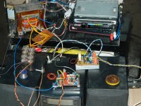
BTW on my built I find-out the relay line coil (supply) was warming up, other than that it works just fine. I am also using a 24V 10ampere relay on 220V AC mains.

I will be checking it on your site.
BTW on my built I find-out the relay line coil (supply) was warming up, other than that it works just fine. I am also using a 24V 10ampere relay on 220V AC mains.
Last edited:
hi every body
i am confusing in class D amp
some body help me
i like have one amp in class D
100W 4ohm
please do some thing guys
thanks
i am confusing in class D amp
some body help me
i like have one amp in class D
100W 4ohm
please do some thing guys
thanks
hi guys these two links can be of help 😀 😀 😀
diysmps.
http://www.diyaudio.com/forums/class-d/166214-ucd-25-watts-1200-watts-using-2-mosfets.html
diysmps.
http://www.diyaudio.com/forums/class-d/166214-ucd-25-watts-1200-watts-using-2-mosfets.html
Hi Fredos,
my coil is T106-2 core ordered from USA and 63 turns = 54uH that's the material you advice for switching amp isn't it ?
When you tell a bigger cap you mean 680n or 1u ?
= decrease cut off frequency of the output filter to minimize ripple at the output , that's it ?
Yeah ! the sound is great bass are deep and high are very clear...
very surprised of the result on a single sided board.
No real life high power test : only small jbl at home ;-) .
Thanks a lot.
The next step is overload protection setup...
Learning a lot about class d amp.
just a bit affraid to push it to clipping (bad experience before : 4 fets and 2 drivers blown...).
do you think duty cycle limiter is necessary to avoid clipping ?
Alexis.
Try air cored coil from one of Your speaker crossovers. It will heat itself a little, depending on DC resistance, but it will never go into saturation. Then try to use 5 100nF foil capacitors instead of one 470nf. Smaller capacitors have bigger specific ripple current allowed. also decouple PS not only + to - but also to the cold side of the filter capacitor, using also several smaller capacitors. Reduce loop area of those decoupling networks by tight mounting. Forget the PCB, use spider web technique..., all in the air, but with short and fat connections.
- Home
- Amplifiers
- Class D
- IR2113 blowing ! help needed...