alexclaire said:Hi Lindomar,
Amp works fine, got 600 WRMS with 4 ohms load (+-80VDC 1KVA power supply).
I'll send Schematics as soon as i draw it ;-)
thanks for your interest...
Alexis.
Front end is Fredos D1200
and power stage is based on Crest LT amp series (4070+IR2113)
Hello Alexis.
Didn't you still draw the schematic of the amplifier?
I will be awaiting.
Thank you very much.

Power supply in HVI is not regulated. It just have minimum load detection that switch the power supply between normal operation and hickup mode. On my 10 kW beast, regulation is done on the PFC section, but it include the switching power supply that run at 50% duty cycle without inductance at rectifier. Primary voltage of the switching, ie output of PFC vary to keep constant voltage at output of switching. Their is only one overall feedback loop for booth stage.
The regulation on my amplifier topology is not needed because I design the front stage of the amplifier (the same as alexclaire use) to work as a linear amplifier with PWM power stage. Performance are comparable to linear amplifier with effiency of PWM amplifier. That's nice that alexclaire have try it. He can confirm performance of my design! He seem to have open his eyes to another way to do PWM amplification! Everybody seem only stick on the UCD way, that I think is not the better way to do switching amplifier. Variation in switching frequency bring a lot of variation in amplifier parameter, specialy near clipping and when you use multiple different idle frequency amplifier. And worst, they are dependent too of power supply regulation and dead time inside amplifier.
My design avoid all these drawback, dead time variation and power supply stability are corrected by the feedback loop, so no need to have a 0.0001% regulated power supply and 1ns trimed dead time on each module to get same performance. You can trim dead time for best effiency and use hight effiency 50% switching power supply in that way.
Fredos
www.d-amp.com
Thanks Alex. 🙂 🙂 🙂 🙂 🙂
The image this a little quality...
Does have as sending with more quality?
You this developing the overload protection in level DC also?
Lindomar.
The image this a little quality...
Does have as sending with more quality?
You this developing the overload protection in level DC also?
Lindomar.
Hello Alex..
??????????????????????????????????????????
I think has something wrong in the schematic.
In the picture of your amplifier has 6 circuits integrated.
And in the schematic only has 5 circuits integrated.
The components are illegible.
Front end:
1-TL072 - > Operational Amplifier
1-CD4060 - > Oscilator
1-LM319 - > Comparator
Power Stage:
1-CD4070
1-IR2113
Lindomar.
Hi lindomar,
you're right !
NE555 for the overload protection isn't shown in the schematics (5s timer when overcurrent is detected)...
Components values are from Fredos have a look in the forums you'll find them
for the power stage have a look at LT crest series schematics.
overload protection schematics is coming...
Lindomar,
Overload detection is onboard and I developped another board with start delay, DC protection, Temperature sensor and fast shutdown to avoid noises in loudspeakers when powering off the amp...
+/-10V, +15V and 12v referenced to -80VDC are also on another board to avoid temperature rising with resistors and zeners...
Alex thank you very much for the answers.
He would have like you to post the schematics again with more quality or send my email lbaudio@uchoanet.com.br PLEASE.
Will you send the rest of the schematic?
Do you have MSN?
I am not a lot of expert in electronics like YOU and FREEDOS.
Lindomar.
He would have like you to post the schematics again with more quality or send my email lbaudio@uchoanet.com.br PLEASE.
Will you send the rest of the schematic?
Do you have MSN?
I am not a lot of expert in electronics like YOU and FREEDOS.
Lindomar.
Hi
be careful,
2 mistakes detected in my schematics:
1) 4060 output signal must be taken on pin 4 (16 MHz divided by 64) (instead of pin 6)
2) R3,C3 must be connected to U1:B in+
in+ mustn't be connected to ground (U1:B mounted as follower)
be careful,
2 mistakes detected in my schematics:
1) 4060 output signal must be taken on pin 4 (16 MHz divided by 64) (instead of pin 6)
2) R3,C3 must be connected to U1:B in+
in+ mustn't be connected to ground (U1:B mounted as follower)
Hi fredo,
i didnt try ucd yet.
I decided to begin using constant frequency but old school class ad using integrator to sum feedback and audio and then to modulator.
All problems with my prototype i fixed reading your theads.So i believe your circuits and know the sound must be good .
Right now , im using your front end to build a small version ,but class ad.In a few days i wiil tell you how it sounds.
By the way,Alexclaire used your topologie in class bd without 555 power suplly in 2113 or i´m wrong?
hi
yes i used fredos front end driving 4070 and IR2113...
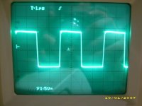
Sound is clear,deep bass and very power full 146Vpp with +-80V rails.
his topology is very easy to understand and results are great.
very smart design !
try it you will be surprised (the right way !)
Alexis (alexclaire)
yes i used fredos front end driving 4070 and IR2113...
Sound is clear,deep bass and very power full 146Vpp with +-80V rails.
his topology is very easy to understand and results are great.
very smart design !
try it you will be surprised (the right way !)
Alexis (alexclaire)
- Home
- Amplifiers
- Class D
- IR2113 blowing ! help needed...