Charles, I think I have already said them as 2 resistors ,one series with input, second one from the output filter to the inverting input of comparator and one integrating cap parallel with that resistor.....from the filter output to -input of comparator
Also I would also use inverse parallel schottky diodes from -Input of Comparator to the ground to prevent overdrive during clipping...😉
Also I would also use inverse parallel schottky diodes from -Input of Comparator to the ground to prevent overdrive during clipping...😉
Hi Charles,
Since Fredos amp uses Grounded Bridge topology, does'nt it generates high EMC as the Rails are Floating with respect to the Grounded side of bridge.....
What do you think?
regards,
K a n w a r
Since Fredos amp uses Grounded Bridge topology, does'nt it generates high EMC as the Rails are Floating with respect to the Grounded side of bridge.....
What do you think?
regards,
K a n w a r
fredos said:Hi Gyula
Power supply is design to provide full power for about 15 minute without thermal overload. Normal operation involve means of 30% power, so power supply is under loaded and most of the time work in Hickup mode.
Fredos
www.d-amp.com
Hi Fredos...
What is "Hickup Mode" in Power supply....
Please explain...
regards,
K a n w a r
Hickup means that power supply work for fews cycle, then shut off, then work for fews cycle, etc. In this way, effiency is greatly improved, and the way I have implement it, keep voltage stable anyways, unless more power is needed. In this case power supply work in normal way.
Fredos
Fredos
fredos said:
Wish that anwser all your question. Price list was on web site, under contact us.
Fredos
www.d-amp.com
Fredos, stop promoting your goods in the regular forums.

/Hugo
hi Fredos,
Still experimenting on my class d amp based on your D1200 front end design...
Changed the fets for IRFP240 (IRFP 4227 before) : no change
placed ground plane under output inductor: no change
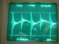
at idle output signal is 250kHz sinus 3Vpp with ringing at 12Mhz (20Vpp) every half period, how could I get rid of theses oscillations ?
My filter is 54uH T106-2 core and 470nF MKP
otherwise sound is great but LF output sinus signal is polluted by these ringings...not audible ;-)
still testing the unit at 580WRMS@1kHz (4 ohms load)
thanks.
Still experimenting on my class d amp based on your D1200 front end design...
Changed the fets for IRFP240 (IRFP 4227 before) : no change
placed ground plane under output inductor: no change
at idle output signal is 250kHz sinus 3Vpp with ringing at 12Mhz (20Vpp) every half period, how could I get rid of theses oscillations ?
My filter is 54uH T106-2 core and 470nF MKP
otherwise sound is great but LF output sinus signal is polluted by these ringings...not audible ;-)
still testing the unit at 580WRMS@1kHz (4 ohms load)
thanks.
Attachments
If you play too much with gate resistor, you will slow down the rise and fall time of you waveform. If you cant reduce deadtime trought the gate resistor, go at the input of the 2113. A good first attempt for dead time is to measure the current at idle with a load, no signal. Optimum point will be the lowest current. Booth gate may not be the same value due to difference in the 2113 delay!
Fredos
www.d-amp.com
Fredos
www.d-amp.com
thanks a lot Fredos,
gonna check this and try...
do you think dead time is a bit much or not enough ?
gonna check this and try...
do you think dead time is a bit much or not enough ?
fredos said:Hickup means that power supply work for fews cycle, then shut off, then work for fews cycle, etc. In this way, effiency is greatly improved, and the way I have implement it, keep voltage stable anyways, unless more power is needed. In this case power supply work in normal way.
Fredos
For how much time its shut off and for how much time its in working mode...
Alexclaire
Not enought and too much can do the same effect...
Workhorse
On and off time depend of the load...At low level and idle, this could be every 2-3 second, always on at full power!
The trick is to do a regulated PWM power supply without rectifier inductance, with 10% more turn ratio on TR than DC buss needed!
Feedback should be as ''dry'' as possible!
Fredos
Amplifier prototype is ready for final module ;-)
just need 2 modules clock synchronised.
Sound is very great ! no more problem at clipping !
144Vpp @1kHz (4 ohms load) !
Mosfet temp rise very low !!
Thanks for all Fredos and long life to D-AMP
don't worry for the critics just go ahead...
Alexis.
just need 2 modules clock synchronised.
Sound is very great ! no more problem at clipping !
144Vpp @1kHz (4 ohms load) !
Mosfet temp rise very low !!
Thanks for all Fredos and long life to D-AMP
don't worry for the critics just go ahead...
Alexis.
I know Alexclaire! Most people just believe in the theorical way to design! Imagination ( and beer!) most of the time bring news great idea on how to do better! Just imagine how much inovation I have in the 12 Kwatts!
Fredos
www.d-amp.com
Fredos
www.d-amp.com
Fredos,
I can imagine the way you work ;-) , the way great improvements have been done in earlier physics (I'm teacher ;-) ).
Don't pay attention to these people always trying to find out problems, the results are here to proove the efficiency of your design...
Have a nice day !
Alexis
I can imagine the way you work ;-) , the way great improvements have been done in earlier physics (I'm teacher ;-) ).
Don't pay attention to these people always trying to find out problems, the results are here to proove the efficiency of your design...
Have a nice day !
Alexis
Hi alexclaire
Could you show us schematic?
I would like to know how/if you did increased dead time of IR.
How did you solved the ringing?
Could you show us schematic?
I would like to know how/if you did increased dead time of IR.
How did you solved the ringing?
Hi luka,
clock generator and pwm modulator are from d amp 1200 (Fredos) and output stage is from Crest LT series schematics available on the net...
output ripple 1,6vpp was normal (+-80V square wave @250kHz filtered with LC with f0=25kHz means -40dB so near (1/100)*80 sinus wave ripple)
30Vpp ringing were generated at each switching, I lowered them by increasing gate resistors to 65 ohms same resistor for each side.this setting was made with adjustable resistor till ringing felt to a minimum that is 3Vpp.
I couldn't get much better I think...
I don't have drawn schematics yet so have a look at fredos's and Crest's ones ;-)
I have been looking for schematics of Crest LT amps, but all I found were pass. protected or not there anymore. Are you sure they can be get of the net?
luka,
here is one link to lt schematics,if it doesn't work send me your mail adress I'll send it to you
Alexis
http://www.epanorama.net/links/audiocircuits.html
here is one link to lt schematics,if it doesn't work send me your mail adress I'll send it to you
Alexis
http://www.epanorama.net/links/audiocircuits.html
- Home
- Amplifiers
- Class D
- IR2113 blowing ! help needed...