Hi alexclaire
Very interesting project. Nice PCB 😎
I think fredos is right about the 1N4148 for gate diodes. In my circuits these have been no problem.
Is the amplifier loaded when you drive it to clipping?
Is there no problem in driving it quite hard (but nor going into clipping) in a 8 ohm load?
Are the mosfets getting hot at any condition.
In idle, with no load they should not get more than luke warm, otherwise, I think you have shootthrough.
I have experimented a bit with IR2110, and I had to add additional dead time with some IRF640 to avoid shoot through (which I think is faster than the types you are using).
Are you sure it is not the fets that are giving in first, and dragging the driver down in the fall?
I'm not too sure about the fets you are using, have you tried some cheap ones like IRF640, IRF540 or the like?
I would maybe try these out, with a lower Vcc/Vss just to make sure things do work, before going to +-80V whoch is quite a lot (~400 W @ 8 ohm)
And as fredos suggests, some decoupling near the fets would be good (cant see whether that is already the case in your design).
Have you tried putting a scope on the mos output?
If it's not self oscillating, I think you should maybe try to disconnect the feedback until everything else works.
Looking forward to hearing more about this project 😉
class d amp
Hi,
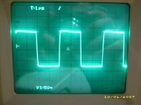
The signal before the output coil is very clean at idle: 50% duty cycle, +80v -80V with no ringing at all...
Fets and output coil are cold at idle.
Coil remains cold at 350WRMS@8ohms but fets become a little warm (temp rise ~20°C).
I m gonna add 470nF capacitor between +Vcc and -Vcc as close as possible to the fets.
Any other advice ?
Thanks for the support ;-)
Hi,
The signal before the output coil is very clean at idle: 50% duty cycle, +80v -80V with no ringing at all...
Fets and output coil are cold at idle.
Coil remains cold at 350WRMS@8ohms but fets become a little warm (temp rise ~20°C).
I m gonna add 470nF capacitor between +Vcc and -Vcc as close as possible to the fets.
Any other advice ?
Thanks for the support ;-)
Hi Baldin,
yes I'm not sure if the driver blow before fets...
I 'm gonna make all the changes i said and see...
yes I'm not sure if the driver blow before fets...
I 'm gonna make all the changes i said and see...
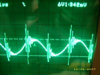

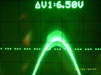
I've disconnected feedback loop and this overshooting over 35Vp output signal disappeared...so problem may be here
Q: The modulator is from D1200 d amp amplifier (Fredos), is it normal that feedback loop (12K//47pF) is from post filter to LM319 (comparator) input (where signal from TL072 buffer is connected too ?)
usually feedback loop ends to the input opamp...
Thanks for reply...
Q: The modulator is from D1200 d amp amplifier (Fredos), is it normal that feedback loop (12K//47pF) is from post filter to LM319 (comparator) input (where signal from TL072 buffer is connected too ?)
usually feedback loop ends to the input opamp...
Thanks for reply...
Yeah! That's the purpose of the low amplitude triangle wave...All error correction are done by the LM319, this eliminated the group delay of the opamp. The opamp is just to give gain to the overall amplifier, the power stage gain have only about X20. Ringing at 35V is due the saturation of your coil or hight ripple of your output cap. Try a bigger one and everything should be fine. Work well now? Like the sound?
Fredos
www.d-amp.com
Fredos
www.d-amp.com
Hi Fredos,
my coil is T106-2 core ordered from USA and 63 turns = 54uH that's the material you advice for switching amp isn't it ?
When you tell a bigger cap you mean 680n or 1u ?
= decrease cut off frequency of the output filter to minimize ripple at the output , that's it ?
Yeah ! the sound is great bass are deep and high are very clear...
very surprised of the result on a single sided board.
No real life high power test : only small jbl at home ;-) .
Thanks a lot.
The next step is overload protection setup...
Learning a lot about class d amp.
just a bit affraid to push it to clipping (bad experience before : 4 fets and 2 drivers blown...).
do you think duty cycle limiter is necessary to avoid clipping ?
Alexis.
Hi Fredos, hi Alexclair.
It's really interesting thread.
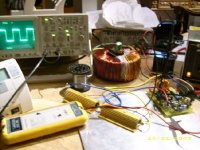
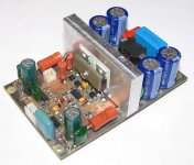
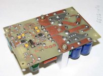
Now i try to built amp with similar schematics (based on d1200).
Use irs20124 as mosdriver, pn28nq15n (fast, low rds(on) and lowcost switch from philips). Carrier freq 250kHz.
Seems to me, it'l be simple, reliable amp for home sub with output power range about 300w*4Ohm, ~200-250w*8Ohm.
Basic limitation is "high side floating supply voltage" of mos driver and it's output current, 200V, 1.2A short circuit.
Here is some foto:
It's really interesting thread.
Now i try to built amp with similar schematics (based on d1200).
Use irs20124 as mosdriver, pn28nq15n (fast, low rds(on) and lowcost switch from philips). Carrier freq 250kHz.
Seems to me, it'l be simple, reliable amp for home sub with output power range about 300w*4Ohm, ~200-250w*8Ohm.
Basic limitation is "high side floating supply voltage" of mos driver and it's output current, 200V, 1.2A short circuit.
Here is some foto:
Attachments
What I means by bigger output cap is MKT with same value but lower ESR. You can do the same by // 5X 0.1Uf 250V to get lower ESR. ESR is important to avoid switching pick-up in feedback loop. At a certain power coil begin to saturate and create ringing itself. Bigger size core avoid this, or simply add a ground plane under the coil directly to the power supply ground.
Clipping is not a probleme untill you have enought ''holding'' capacitance in your bootstarp circuit. The original circuit of the D-Amp 1200 do not suffer from this because it use P-N power mosfet with direct drive....But old model 1600 and 2000 use all n channel mosfet, with 6N137 and TC4429 mosfet driver in bootstrap design, essentialy same as your circuit, but at higger power to be able to drive mosfet as fast as possible. With thie driver arrangement, I use 100uF on bootstrap and 100uF on lower side drivers without any probleme, even at hard clipping. But dont forget that the limiter cell with the CA3080 help a lot to avoid too long clipping....
Another thing...Try a 47-100pF directly at teh output of the LM319 and LM319 output ref (V- in my case..), this will slow down a bit the rise time and fall time of the amplifier and avois some coil ringing probleme...
Wish that help you a lot!
Fredos
www.d-amp.com
thanks a lot Fredos,
Sure it helps a lot ;-)
My bootstrap cap is 47uF ---> gonna add 47uF//.
sound is very great but still afraid of clipping
clipping occurs at 73V peak, only got a 9.4 ohms load --->280WRMS@1kHZ
Do you think lowering output impedance to test power capabilities is safe (4 ohms for example) ?
my overload protection is set to 30A on each fet.
Fast clipping doesn't seem to be a problem but in real life clipping may be longer and a signal limiter at the input is the way I'll go.
other little problem:
I made an auxiliary winding on my toroid to produce 12V referenced to -80V to bias 4070 and IR2113
7812 is not able to do the job (although my lab power supply dispays 12V@50mA !)
can you confirm that there are current peaks over 1A to bias IR2113 (and so charge fet's gates)
in this case 7812 is not a good choice to produce this voltage.
Thanks
Hi Gyula
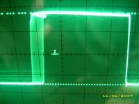
Coil ringing is due to materila going in resonance. -2 material have a close resonance frequency at 260Khz, 520Khz and 1.15Mhz. Runing at 250Khz is close to ringing frequency and harmonic of signal bring it into resonance. This is not a probleme if winding is done in good way, ie with litz wire and tight winding. Adding a ground plane under the coil add capacitance to the winding and nearly cancel this effect. Using coil near is resonance greatly improve effiency of the amplifier. Mosfet work near ZVS and as Alexclaire see, there is no ringing on the squared wave, even without snuber capacitor on the PSU near the mosfet. Lowering or increasing switching frequency will help too to remove ringing, but in my experience, 250Khz is the optimum frequency for effiency.
Alexclaire
I normaly use a cheap resistor-zener regulator for mosfet drivers, but dont forget to add at least 100uF on the low side drivers PSU pins to provide enought peak current to drive booth lower side mosfet and bootstrap capacitor. Your 7812 should be OK if you have this capacitor on lower side drivers...
Fredos
Great! The raised capacitance by the tight winding can't cause resonance?
I wondered the amplifier contains direct, proportional feedback from a second-order loop (LC filter). In ideal case it has near 180 degrees of phase shift at cutoff. And the modulator's linear phase delay is also added to this.
With parasitics, R(esr), R(L), this will be a first order system at upper frequencies. But I think, if L is decreasing, the cutoff goes to higher frequencies, where the modulator's linearly growing phase shift delay will be dominant, and cause instability.
- Home
- Amplifiers
- Class D
- IR2113 blowing ! help needed...