That's why I keep the coil at higher value! Thighter winding as for my experience, diminue oscilation amplitude at resonance....With the ground plane on PCB.
Fredos
Fredos
Hi Fredos,
In your D-amp 1200, you donot use opamp error amp and directly feeding the feedback into the LM319, why its so?....is there any benifit arised by not using the error amp in post filter feedback...and directly controlling the loop through comparator.....
regards,
K a n w a r
In your D-amp 1200, you donot use opamp error amp and directly feeding the feedback into the LM319, why its so?....is there any benifit arised by not using the error amp in post filter feedback...and directly controlling the loop through comparator.....
regards,
K a n w a r
Hmm. Interesting. Maybe the attenuated ringing is due to the increased resistance of the inductor by the tight winding caused proximity. And the ground plane minimize the feeding loop's area. The feeding inductance will be low.
Have you experienced any problem with PD or PID control of the amp., why do you use direct feedback? Only to use up parasitic effects 🙂 ?
Have you experienced any problem with PD or PID control of the amp., why do you use direct feedback? Only to use up parasitic effects 🙂 ?
Workhorse
With a low amplitude triangle wave, you increase the open loop gain of the comparator stage. Using comparator in inverter allow to skip error amplifier stage and all the probleme that this cause and use comparator as comparator/error amplifier. The error point at the negative input of the comparator will never exced in amplitude the level of the triangle wave on the positive input (except at clipping....). So with a 100-300mV triangle wave, you reach near the point of an operating error amplifier stage, without the group delay, phase shift, pole and zero added by the OP amp itself. Just see the circuit as a big analog switching power op amp! (no too long?) The overall amplifier work as a linear amplifier (feedback, etc..) but the power convertion is PWM. That's the reason why the closed loop gain is so low and a pre-amplifier stage is needed. In that way, you can add a lot of deadtime, poor decoupling, poop power supply, bad ground plane, etc, and this will not affect the overall performance of the amplifier. Everything is include in the feedback loop.
Funny that after a years on DIYaudio, somebody just realize that their is no error amplifier and figure that their is other way to do thing, and other way to think how to do it! Next step maybe my HVI schematics...Just to see if it will take so long!
Fredos
That's the reason why the closed loop gain is so low and a pre-amplifier stage is needed.
But the open-loop gain is lower too. One has to keep this in mind. This might not be so critical with your high-power amps since these already have a high opn-loop gain. But with low-power amps this might be detrimental. So one has to decide on a case-by-case basis if its use is recommended.
Funny that after a years on DIYaudio, somebody just realize that their is no error amplifier and figure that their is other way to do thing, and other way to think how to do it!
I did it twenty years ago on a prototype !
Regards
Charles
So this configuration is easy to work with it! Open loop gain is determine by the triangle wave amplitude and closed loop gain by the overall feedback! Playing with booth of them will let you get what you whant! Higger open loop gain means better transient respond (but more sensitivity to parasite on bad design PCB, so intreator cap should be as hight and close to comparator) and lower overall gain means better linearity and frequency respond. Best configuration will be tu use it as a current buffer with a gain of 1, but means the need of a voltage amplifier in front end. I have already built a reference amplifier with this topology for a recording studio, and as now ( 7 years ago!) they have not find nothing more musical than this. The front stage was from an old Marantz analogue amplifier...Really good final result!
Fredos
www.d-amp.com
Fredos
www.d-amp.com
And had you got any problem about your amplifiers in this way can follow constant signals with constant error, and rising signals with rising error relative to the input?
The one purpose of using an error amplifier, one pole at zero, to eliminate this.
The one purpose of using an error amplifier, one pole at zero, to eliminate this.
As from now performance was already excelent, like Alexclaire said, good audio reproduction too! Look at schematics in overall way!
Fredos
Fredos
Yesterday I found out the linearity is probably better in your design, because with the direct feedback, you eliminated a lot of nonlinear elements, whose would be critical for linearity of the overall amplifier, as they would make the sensing of output signal.
And variation of the speaker's impedance is nearly ineffective for the output filter.
And variation of the speaker's impedance is nearly ineffective for the output filter.
That's right. The thing was to think about linear amplifier with switching power operational amplifier configured as standard op amp. That's the way I have follow from the begining, and I still follow it. I found that is the best, easier and simplest way to design switching amplifier. I still use this topology in my last 12Kw 6Kw per channel) amplifier. If you go to [link removed by mod team] and find the class d forum, you will see a picture of a future 10Kw monorail amplifier based on this topology. Please ignore the fews guy that think I dont know what I'm talking about and bring there new theory about EMI emission, just look at the last post when they talk about the ringing on the squared wave and then bring it to the output leg...Funny....As from now, it seem that this topology will whant to work at any power level, with near the same performance!
Fredos
www.d-amp.com
Fredos
www.d-amp.com
Hi Fredos,
Very good explanation, thanks very much...
So it means one could eliminate the error opamp and use the inverting pin of the comparator and it function as a comparator/erroramp both in one.....fantastic......!
Fredos, in your bridge amp with monorail...HVI8000 types...which modulation did you use AD or BD....and do you take the feedback separately from each half of the bridge after the output filter[post filter]] OR
You use a differential opamp feedback scheme.... and apply it to your comparator....
Is your opamp referenced to midpoint of the rail or to the negative ground....
Your contribution is great for all of us who love the technical discussions...and new achievements...
regards,
K a n w a r
phase_accurate said:
But the open-loop gain is lower too. One has to keep this in mind. This might not be so critical with your high-power amps since these already have a high opn-loop gain. But with low-power amps this might be detrimental. So one has to decide on a case-by-case basis if its use is recommended.
I did it twenty years ago on a prototype !
Regards
Charles
Dear Charles,
So it means post filter feedback could be implemented directly to the comparator....
Any points to consider before atempting this in your view?
Could this be implemented in bridge amp using post filter feedback and summing the feedback from both half bridge output nodes with a differential opamp and then feeding directly to the comparator...
OR
Using seperate Half bridges as in BD modulation and applying the post filter feedback to their respective comparators....In this case the comparator should be referenced to the midpoint of the rails[in monorail topology]
It would be great for all members if you share some part of your invaluable knowledge with all the members on this intersting topic.....
regards,
K a n w a r
Output bridge are floating and one side referenced to ground. AD modulation, same input configuration as model 1200.
Fredos
www.d-amp.com
Fredos
www.d-amp.com
Hi Fredos how are You ?
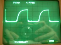
I change the filter Cap for MKP 470nF 630VDC no more hum in loudspeaker at idle...but still peaks on the top of the sinus for voltage over 35Vp.
i got a little question about gate voltage waveform (Vgs)
is it a normal waveform ? see pic... (1/10 differential voltage probe)
Rgate is a bit much maybe (47ohms//1N4148 + 10K//z15V) ? (lowering it will turn fet faster).
Thanks for answering...
Attachments
I forgot...
may the windings made with conventional wires be the source of these oscillations ?
gonna try litz wire but not easy to find...
may the windings made with conventional wires be the source of these oscillations ?
gonna try litz wire but not easy to find...
with 47 ohms gate resistor yes...Implement dead time at the input of the IR drivers and bring these resitor down, maybe in the range of 10-22 ohms...
Fredos
www.d-amp.com
Fredos
www.d-amp.com
fredos said:Output bridge are floating and one side referenced to ground. AD modulation, same input configuration as model 1200.
Fredos
www.d-amp.com
Hi Fredos,
So you use a Grounded Bridge Topology.....
Then you have must taken single feedback from the ungrounded side after the filter only , do you use only one filter or a differential filter....
This is quite interesting Fredos....
Cheers
K a n w a r
So it means post filter feedback could be implemented directly to the comparator....
Didn't mean to imply that. But there is actually a self-oscillyting topology that does indeed feed the filter-output directly (well, almost !) into the comparator : UcD.
If you want to do post-filter feedback with fredo's design you'd have to add some more components (thoug not many) but it could still be implemented mainly passive ! There is only one restriction: You will have to generate the triangular seperately, i.e. you can't feed a rectangular into the same node as the input singal and the NFB anymore.
Regards
Charles
phase_accurate said:
Didn't mean to imply that. But there is actually a self-oscillyting topology that does indeed feed the filter-output directly (well, almost !) into the comparator : UcD.
If you want to do post-filter feedback with fredo's design you'd have to add some more components (thoug not many) but it could still be implemented mainly passive ! There is only one restriction: You will have to generate the triangular seperately, i.e. you can't feed a rectangular into the same node as the input singal and the NFB anymore.
Regards
Charles
Hi Charles,
Yes I already know that UCD is a power comparator....
I always prefer Force Clocked designs.....and have built them using error opamp, now I thinks its much easier for me to apply the feedback directly to the comparator....
any extra components required apart from 2 feedback resistors and the integrating capacitor....
regards,
K a n w a r
any extra components required apart from 2 feedback resistors and the integrating capacitor....
Yes, a LOT ! At least a series resistor with the integrating cap and a parallel cap with the feedback resistor.
Regards
Charles
- Home
- Amplifiers
- Class D
- IR2113 blowing ! help needed...