Hi AllenB,
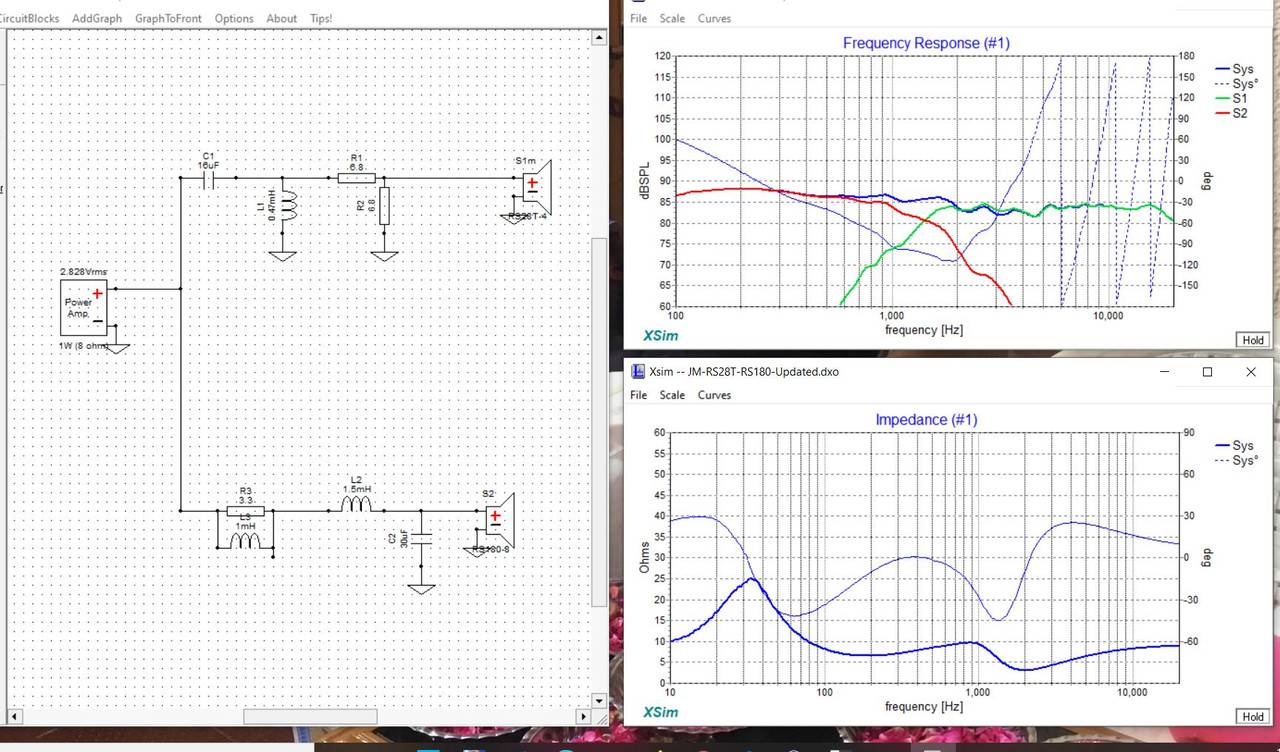
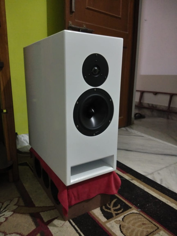
I am putting up a crossover with RST28F-4 and RS180-8 drivers from Dayton, I have attached the crossover and simulation. I see a huge dip in impedance around 2K region can you suggest what is causing it? Or a better approach for this. These are the values from parts Express and I am yet to order the drivers
I am putting up a crossover with RST28F-4 and RS180-8 drivers from Dayton, I have attached the crossover and simulation. I see a huge dip in impedance around 2K region can you suggest what is causing it? Or a better approach for this. These are the values from parts Express and I am yet to order the drivers
I can't see the values but I'd begin by guessing resonance is playing a part in the tweeter response near 2k.
If you disconnect the woofer you can confirm which driver is causing the issue, if it is the tweeter then please show the raw tweeter response overlayed with the crossed tweeter response, as well as the circuit.
If you disconnect the woofer you can confirm which driver is causing the issue, if it is the tweeter then please show the raw tweeter response overlayed with the crossed tweeter response, as well as the circuit.
I have disconnected the woofer seems its been caused by tweeter. here are the values of crossover
RAW Tweeter values
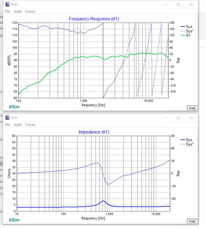
With crossover
RAW Tweeter values
With crossover
Last edited:
Your 2nd order high pass filter resonance is a little high at 1.7 which would account for a lower impedance. It shouldn't be necessary to use resonance that way to boost the knee, because the natural response is 8dB higher there. I'd begin by reducing the value of the capacitor and finding an alternate way of shaping the response.
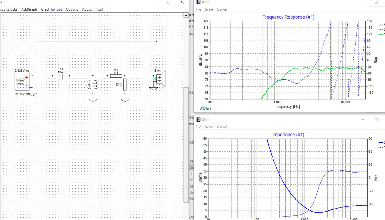
Thanks for the revert, Can I use higher slope for high pass? also changing the capacitor value do increase the impedance however there is a steep dip between 1k to 2k.
Firstly, you can make your plot window look something like the attached image, this way you can see the phase for the two ways.
Next, enter the tweeter driver properties and set the offset. Now you have it as being 3.18 inches forward. Is that correct?
Then, watch for the need to change polarity as you change the responses.
Next, enter the tweeter driver properties and set the offset. Now you have it as being 3.18 inches forward. Is that correct?
Then, watch for the need to change polarity as you change the responses.
Attachments

Yes the tweeter is about 3.18 inches forward.
Let me try to make my graphs similar to yours's Thanks for the inputs
Let me try to make my graphs similar to yours's Thanks for the inputs

I did measured from the top and didnt substracted the value of tweeter. let me remeasure just the woofer cone and redo the simulation
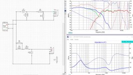
Just measured the woofer cone height and then substract the tweeter one and the value is -1.18. Also I have noted you have reversed the polarity of woofer as well. Here is the updated graph.
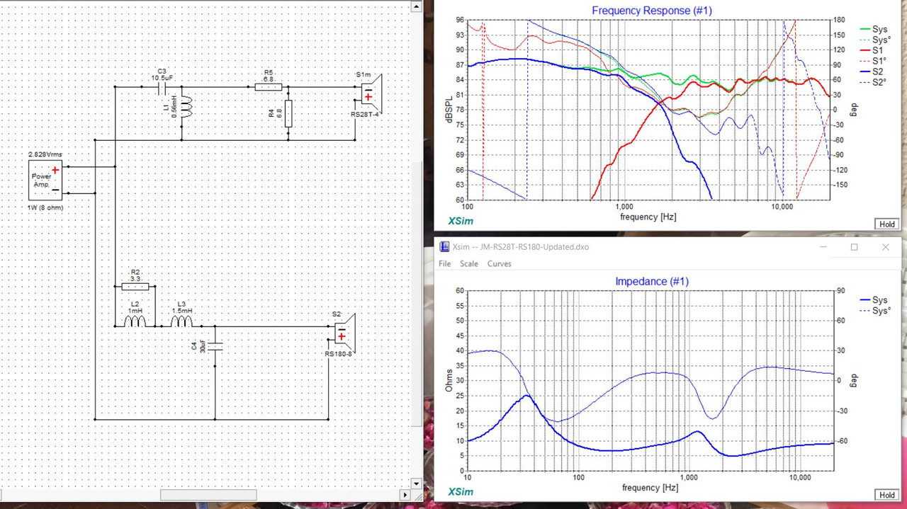
Your impedance dip is now at 5 ohms, very good.
Yes, I changed the polarity on both, they are the same, you can change them back. As long as they are the same it will work. The reason I did that was to make the graph more readable.
Yes, I changed the polarity on both, they are the same, you can change them back. As long as they are the same it will work. The reason I did that was to make the graph more readable.
- Home
- Loudspeakers
- Multi-Way
- Introduction to designing crossovers without measurement