A journey to share.
Going through a learning curve following AllenB's foot path, here is what I'd like to share.
First, read and understand the complete guide. Buy affordable (cheap) drivers for a try. You'd need to remove and install frequently the drivers to tweak crossover for the trials. Get many sizes of resistors and capacitors. I bought copper wires for manual winding the crossover (download the apps to tell you how many turns of wires to get x mH inductor. Making inductors, for me was the toughest part.
Don't dwell too long in calculating the perfect crossover (there isn't any), get your hands dirty and start to build it. I dwelled almost a year in designing this and that, and I looked back it is a waste of time.
Once I really build my first crossover, and adjusting many components to get the sounds I want, and this is the time where I actually "learned".
In short, don't dwell too long in paper work in designing, start building it and start to tweak it,
Remember, start your first step quickly by actually building the hardware.
Have fun!
help with correct wiring of speakers
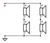
Im posting here because I could not figure out where else to post my question which is I want to wire two 8 ohm woofers out of phase and two 8 ohm fullrange drivers out of phase and hook them all up in a series/parallel configuration to get a total load of 8 ohms. How do I do it? A diagram would be helpful. Thx!
Im posting here because I could not figure out where else to post my question which is I want to wire two 8 ohm woofers out of phase and two 8 ohm fullrange drivers out of phase and hook them all up in a series/parallel configuration to get a total load of 8 ohms. How do I do it? A diagram would be helpful. Thx!
Hello AllenB,
Thank you for all your support and guidance I am very excited to build these speakers.
I have worked out some of the math indicated in your guide, but I am totally lost with the midrange. Can you please help with the component list?
Attached picture shows my working and component types trust it works?
I have not included flattening the impedance as I do not have the component details.
Also for the fine tuning my AV processor can EQ it from 20Hz to 20KHz so I should be able to make small adjustments. Let me know if you still prefer a 6.5" midrange or with the ability to EQ I should go with the 8" it will give me more head room?
Below are the details of the 8" midrange once again:
Really appreciate your help.
Cheers,
Farid
Thank you for all your support and guidance I am very excited to build these speakers.
I have worked out some of the math indicated in your guide, but I am totally lost with the midrange. Can you please help with the component list?
Attached picture shows my working and component types trust it works?
An externally hosted image should be here but it was not working when we last tested it.
I have not included flattening the impedance as I do not have the component details.
Also for the fine tuning my AV processor can EQ it from 20Hz to 20KHz so I should be able to make small adjustments. Let me know if you still prefer a 6.5" midrange or with the ability to EQ I should go with the 8" it will give me more head room?
Below are the details of the 8" midrange once again:
An externally hosted image should be here but it was not working when we last tested it.
Really appreciate your help.
Cheers,
Farid
It's clear that you have experienced this for yourself. The next horizon is acoustic. This is where you develop the potential of the speaker. I only touched on it quickly when discussing the directivity matching at the cross.Don't dwell too long in calculating the perfect crossover
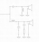
I've shown an example below. This is a way to keep 4 drivers looking like 8 ohms.. Before anyone asks, there is more than one way to do this but the result is basically the same.I want to wire two 8 ohm woofers out of phase and two 8 ohm fullrange drivers out of phase and hook them all up in a series/parallel configuration to get a total load of 8 ohms.
ntell411, I'd like to check something with you as connecting half of the drivers reversed polarity would normally be unusual. However it would be normal if, for example, you were putting half into the box backward, or mounting them on the back panel. This is something that might be done for distortion reduction for example.
Attachments
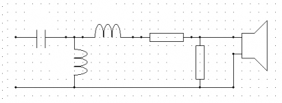
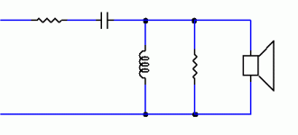
Farid, putting together the midrange crossover is about combining the low and the high sections. Most of the parts don't mind the others being there together, because they are working at different frequencies (eg at high frequencies a capacitor acts like it is a piece of wire).midrange
I see you are using Xsim. This will help you to visualise the effect. Just keep in mind the frequencies where the driver works best. Maybe you could try something like I've attached below. You can change it, just watch the impedance doesn't get too low.
Attachments
Thank you for your reply! My hope is by mounting the 2 woofers face to face and out of phase allowing them to move in a push/pull manner will increase their output and allow me to use one h-frame box instead of two (open baffle.) For the two full rangers, mounting them next to each other but in opposite directions should help increase power handling and reduce distortion.
Yes, then this is correct.
This is going off topic but when you put the drivers face to face you can increase force, but this is not what is needed in free air. For open baffles it can help to move more air putting the drivers side by side.
This is going off topic but when you put the drivers face to face you can increase force, but this is not what is needed in free air. For open baffles it can help to move more air putting the drivers side by side.
My 2010 Crossover
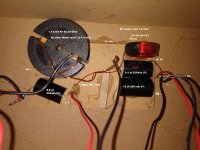
Allen can you please draw the diagram of this crossover? I can't see it, the 1 ohm resistor connected across two capacitors in what I think are parallel and the other ends are wired all together, IN-, W-, TW-.
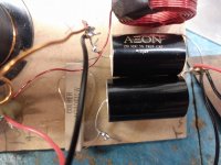
It is supposed to be a 2 way crossover with a single 6 ohm tweeter and two 4 ohm woofers wired in series. The woofers need replaced, I was hoping to use the tweeters and crossovers with modifications if needed. I read your Flattening the tweeters impedance in the forum , tried to apply the math and get gibberish. I bought a "Multi-Function Tester -T7 H" from ebay the inductor readings confuse me. the capacitors and resistor test as labeled still close after ten years, I was told production stopped for these speakers in 2005.
If I can't use anything it's ok, I just want to understand the crossover. I want to learn from it, I think from reading your tutorial, mistakes are in this xover.
Thank You
Allen can you please draw the diagram of this crossover? I can't see it, the 1 ohm resistor connected across two capacitors in what I think are parallel and the other ends are wired all together, IN-, W-, TW-.
It is supposed to be a 2 way crossover with a single 6 ohm tweeter and two 4 ohm woofers wired in series. The woofers need replaced, I was hoping to use the tweeters and crossovers with modifications if needed. I read your Flattening the tweeters impedance in the forum , tried to apply the math and get gibberish. I bought a "Multi-Function Tester -T7 H" from ebay the inductor readings confuse me. the capacitors and resistor test as labeled still close after ten years, I was told production stopped for these speakers in 2005.
If I can't use anything it's ok, I just want to understand the crossover. I want to learn from it, I think from reading your tutorial, mistakes are in this xover.
Thank You
Attachments

Farid, putting together the midrange crossover is about combining the low and the high sections....
Thank you AllenB the diagram and info will help tremendously. I will keep working on it to try and get it right.
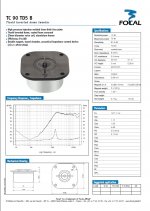
I should be able to get the frequency response of both the 8" midrange (DS18 PRO-X8.4BM) and tweeter (DS18 Pro-TW120B) from DS18 Audio.
But may have to take some measurements for the Rockville Woofer (Rockville RVP15W4) this weekend, I got a UMIK-1 and have REW ready to go.
Once I have some measurements I will share the frequency response graphs for your review and valuable feedback. Although I don't think I will be able to get the impedance measurements - that is the challenge with these car audio components.
Cheers
It's always tricky doing this from photos so please double check this.Allen can you please draw the diagram of this crossover?
I see you are getting uncertain readings from the coils. You are measuring resistance and inductance. When doing resistance, first bring your meter leads together and measure them on their own. You might measure a fraction of an ohm, which you need to subtract from any measurements. Make sure you make clean and firm contact on the inductor leads or when doing any low resistance measurements. You don't want other parts of the circuit to be working across the inductor at the same time. When doing inductance measurements, move it into a non metallic place and hold still while the measurement settles.
Attachments

Thank You so much
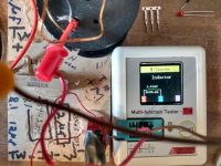
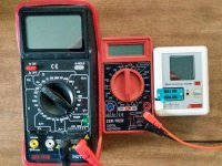
With my meter set at lowest 200 ohm setting shorting the leads gives 1.0 Ohm.
Tweeter inductor measured resistance shows 1.4 to 1.5 ohm minus the 1.0 from meter leads results in .4 to .5 ohm. I don't know what that reading means.
Woofer Inductor measures 1.8 ohm minus 1.0 results in .8 ohm.
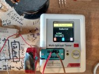
Using the Multi Tester T7-H with the YouTube
LCR T7 - Multi-Function Tester - YouTube video I get.
Tweeter Inductor 0.35 mH, R-7.86 Ohm ( I am not sure what that means).
Woofer Inductor 1.41mH, R=93.6 Ohm.
Resistor reads 1.01 Ohm.
The resistance readings between the HF meter and the Tester are not even close.
No markings on either inductor unless in the glue.
Do these reading make sense to you, are they in the Ball Park for Harbor Freight and a Multi tester?
With my meter set at lowest 200 ohm setting shorting the leads gives 1.0 Ohm.
Tweeter inductor measured resistance shows 1.4 to 1.5 ohm minus the 1.0 from meter leads results in .4 to .5 ohm. I don't know what that reading means.
Woofer Inductor measures 1.8 ohm minus 1.0 results in .8 ohm.
Using the Multi Tester T7-H with the YouTube
LCR T7 - Multi-Function Tester - YouTube video I get.
Tweeter Inductor 0.35 mH, R-7.86 Ohm ( I am not sure what that means).
Woofer Inductor 1.41mH, R=93.6 Ohm.
Resistor reads 1.01 Ohm.
The resistance readings between the HF meter and the Tester are not even close.
No markings on either inductor unless in the glue.
Do these reading make sense to you, are they in the Ball Park for Harbor Freight and a Multi tester?
Attachments
AllenB quick question is it worth getting a Dayton DATS V3 for impedance measurement if one intends to build speakers as a hobby?
I still can't see it
I still can't understand your drawing and what I see on the crossover.
The 1 ohm 10% 10 watt resistor is wired together with In+ W+ and the 9.1uf capacitor and one end of the 1 ohm 10% 10 watt resistor, the other end of the resistor is wired to one end of the 12uf capacitor.
The opposite end of both capacitors are wired together along with the TW-, In- and W-. In your drawing I don't see the resistor connected to both capacitors.
Please explain.
Thank You.
Attachments
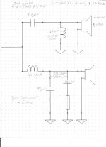
It makes no difference which way the resistor and capacitor are drawn because they share the same current path. I should have considered that.
However you should see that the resistor connects to both capacitors. The ground symbol is important. Every time you see it you should imagine that they are all connected together. This is a good symbol because it keeps the schematic tidy.
However you should see that the resistor connects to both capacitors. The ground symbol is important. Every time you see it you should imagine that they are all connected together. This is a good symbol because it keeps the schematic tidy.
There is something wrong with your test setup. It isn't very interesting (at this level) to see the resistance of the inductors, but it is important to know the device is working properly. Your meter was giving useful readings.R-7.86 Ohm
Impedance measurement is useful to calculate the way the crossover interacts, as you want when you simulate a crossover. There are different ways to get that information. Copying the datasheet works for some drivers, where others (for example horn drivers) the impedance changes considerably when you put them in their enclosure so you need to measure it. With woofers, the bass region impedance changes with the box, but it doesn't matter because the crossover is at the higher frequencies. However it would matter with a midrange driver in a box.getting a Dayton DATS V3 for impedance measurement
The product you mention could make it easier. I don't use anything like it so I'm assuming. A measurement microphone is a good thing to have.
It makes no difference which way the resistor and capacitor are drawn because they share the same current path. I should have considered that.
However you should see that the resistor connects to both capacitors. The ground symbol is important. Every time you see it you should imagine that they are all connected together. This is a good symbol because it keeps the schematic tidy.
There is something wrong with your test setup. It isn't very interesting (at this level) to see the resistance of the inductors, but it is important to know the device is working properly. Your meter was giving useful readings.
Wow, I see it now, I see it because in the picture all the wires are twisted together sharing the same current path. I am starting to understand it. I have been reading your Introduction to designing crossovers without measurement up to post 11.
I see no resistor in the tweeter circuit or did I read the diagram incorrectly?
About the Multi Function meter, I have no control what it displays or if the resistance was important. it cost $15.00 usd on ebay eBay item number:274392004446
The Harbor Freight digital meter is free when you buy something,
the point I was trying to make is I don't have expensive precise tools.
Thank You so much for explaining and writing this tutorial.
Getting a good crossover isn't simple, but precision is not the answer. Give me a meter that has 10% error and I'll get 90% of the way in the design. Yours, however, is showing very suspect resistance numbers. How was the calibration process?
...
The tweeter schematic is shown below. There are two resistors.
...
The tweeter schematic is shown below. There are two resistors.
Attachments

My humble comments and 2cents please. While it is true AllenB has created a very good guideline, we owe it to him by reading and understanding it. We should not be dwelling to questions which have been explained well in the guideline. More importantly, we should be asking relevant questions, not a question like how to use this multimeter and how to draw schematic. We can ask these type of questions to another forum. No pun intended.
Cheers...
Cheers...
My apologies
I may have not explained myself clearly, I don't see a resistor in the diagram of MY crossover, you were kind enough to draw for me, unlike your diagram in your post 11 that has resistors.
Secondly I used three different meters, two Harbor Freight digital meters and the Multi-function tester. I agree with you, each one displays completely different readings, my apologies for the confusion. I don't have accurate test equipment. I am just trying to learn.
I want to keep the tweeters for now because they fit the hole in the box. I have replaced the tweeter voice coil three times since 2010.
I found replacement woofers that fit the cutout in the box.
I learned more about speakers and crossovers reading eleven of your posts than any other articles. I bought the first book on speaker building in 2004.
Your explanation of impedance is brilliant "impedance is the same as resistance except that it applies to alternating current like music signals. Impedance can be a combination of plain resistance, inductance, and capacitance. The difference being that resistors behave the same at all frequencies but inductors and capacitors have a varying effect that shows greater influence at higher or lower frequencies."
I struggled to understand impedance in school, at Amature radio meetings online . Your tutorial and help tells me I can do this.
I don't really know how to measure an inductor, this was my first time.
Getting a good crossover isn't simple, but precision is not the answer. Give me a meter that has 10% error and I'll get 90% of the way in the design. Yours, however, is showing very suspect resistance numbers. How was the calibration process?
...
The tweeter schematic is shown below. There are two resistors.
I may have not explained myself clearly, I don't see a resistor in the diagram of MY crossover, you were kind enough to draw for me, unlike your diagram in your post 11 that has resistors.
Secondly I used three different meters, two Harbor Freight digital meters and the Multi-function tester. I agree with you, each one displays completely different readings, my apologies for the confusion. I don't have accurate test equipment. I am just trying to learn.
I want to keep the tweeters for now because they fit the hole in the box. I have replaced the tweeter voice coil three times since 2010.
I found replacement woofers that fit the cutout in the box.
I learned more about speakers and crossovers reading eleven of your posts than any other articles. I bought the first book on speaker building in 2004.
Your explanation of impedance is brilliant "impedance is the same as resistance except that it applies to alternating current like music signals. Impedance can be a combination of plain resistance, inductance, and capacitance. The difference being that resistors behave the same at all frequencies but inductors and capacitors have a varying effect that shows greater influence at higher or lower frequencies."
I struggled to understand impedance in school, at Amature radio meetings online . Your tutorial and help tells me I can do this.
I don't really know how to measure an inductor, this was my first time.
Attachments
- Home
- Loudspeakers
- Multi-Way
- Introduction to designing crossovers without measurement