Congratulations.
If you sink the Follower CCS current into the Unregulated supply (Which hardly matters for noise cause the CCS is high impedance), you can get away with a shunt out of two 85A2 set by a DN2540 cascode CCS for the grid bias. Simple and practically impossible to beat.
Thank you!
Yes, good idea indeed, but I would need a dumb-proof schematic... Just can't design power supplies by myself...
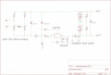
There you go.
You can tweak the R1 somewhat higher, but in reality it wont make any audible difference.
R6 and R7 can be used to shunt some current away from the 85A2 if you need more than they can shunt. Otherwise i suggest mounting 2.2MEG 1W metal films there to aid in the start up of the tubes.
C3 is not critical if you stay below about 22nF your on the safe side, Above say 47n you have the chance of building a neon relaxation oscillator.
Attachments
Last edited:
Is there an advantage of having two 85 volt regulator tubes over a single 150 volt one? Those few volts more or less shouldn't matter too much
The 85A2 takes the 0A2 150C2 to the woodshed in terms of noise performance. They are cheap plentiful if you know where to look. I pick these up at swap-meets for 25c and nobody realizes just how balls to the wall awesome they are.
I used them in a RIAA tube preamp tube voltage regulator i did and i got under 1PPM noise total. Sub 300uV noise plus hum with tubes and some sand. At about 325V out, 40mA load. Input noise for the regulator part was several volts PP but i have trouble remembering.
In actuality its noise figure expressed in PPM takes many (90-95%) modern voltage references to the same said shed. With the notable exception of some buried Zener references that have different corner noise from run of the mill bandgap references. Examples of this are LM399 or LTZ1000?
The problem with any solid state regulator is that the reference noise gets amplified by approx the amplification factor of the control electronics. Moreover you need quite an expensive solid state reference to make sure it doesn't have any "Popcorn noise"
I have some LTZ1000 in a drawer somewhere...
But what makes the 85A2 so much better than its 150 volt (or 105 volt) counterparts? Down the line they all use the same physics to do their thing.
But what makes the 85A2 so much better than its 150 volt (or 105 volt) counterparts? Down the line they all use the same physics to do their thing.
Those counterparts of which you speak, For convenience say 0B2 and 0A2 are Stabilizer tubes that are meant to shunt currents of 5..30mA instead of a REFERENCE tube that was designed to provide a system reference point and have ultra low noise doing it. If you use it right you can keep the voltage within 10mV or so over 10000 hours.
The 85A2 is optimized for 3mA current. If you run it at that exact current it will maintain its output voltage between 0.01% over 1000 Hours of operation. Thats a long term drift figure of 100PPM for a product made in 195X However if you overload it say at 10mA it will take some time to reach these figures again.
The 85A2 was a Philips product and the Pinnacle of what was achievable at the time.
I have to take my hat of to the engineers that made the Tektronix tube oscilloscopes, they figured out a way to make a product that had just one ultra stable reference for all the supply buses. It is not uncommon to measure the -150V reference bus on one of those scopes and measure it years later, and have it within 0.2%.
Building anything at those voltages that even comes close to the noise and drift performance gets hairy and expensive fast. You would be looking at a solid state voltage reference of more than €10 just to get the reference noise for the regulator low enough that if you amplify it say 17 times. You get the same number.
You could of course take a cheaper reference and a good op amp (€5-10) and RC filter the heck out of the reference voltage before its fed into the voltage comparator stage. But that hurts your DC accuracy because the reference becomes high impedance, and any shift in the input bias current is going to produce an error that is amplified multiple times in the feedback loop, just to name a problem on the top of my head. A few pA input bias shift with temperature over a 10K RC resistor amplified multiple times will produce an error.
During my time at university, we had a guest lecturer over who tried explaining the complicated way they were building current sources for electron microscopy, i believe the noise figure they where aiming for was about where the 85A2 is in terms of noise expressed in PPM.
Last edited:
Just to be clear these gas regulator tubes are voltage references, not much rectifying going on in them. You need the diodes anyway 🙂
> The 85A2 was a Philips product and the Pinnacle of what was achievable at the time.
Yes, other cold cathode tubes can't do this at all.
But claiming (without measuring) a noise level of 300µV is not likely to be met using the application circuit you have drawn, simply because the 100/150/200/300Hz (etc) ripple spurs will dominate.
The practical disadvantages should also be highlighted, for anyone else:
- power supply hum-rejection is moderate - to be kind to it.
- Other cold cathode stabilisers come nowhere near the 85A2, and no tubes of this kind are in current production. If the supply runs out - no substitutes are likely be available.
- 170V is quite a way from the -110 to -120V we are now expecting at the GM70 grid, so more padding resistance will need to be added to the output impedance, making it susceptible to pickup.
- 85A2 is Mechanically fragile.
Silly scare stories about noise in modern regulators do not apply to my regulator designs, which are based on my known-good positive regulators.
The bias regulators will be 100% tested for noise, and going by the positive version's results, it will be a good bit lower than the 300µV rms level even including the mains line-voltage spurs (100/120Hz etc). IOW, you get guaranteed performance out-of-the-box, if the specified winding voltage & raw DC values are used.
The regulator is supplied tested & ready to plug in and go. It is adjustable to any voltage, and the performance does not degrade for different input-to-output voltages.
Regulator size is 37mm x 73mm and 12mm high (about 1.5" x 3" x 0.5") - easy to fit in the chassis.
The bias regulator can be fed directly from the Raw DC doubler for the Source-Follower's supply. (250V DC); the transformer winding is 85V rms in this case.
Can't comment on the other stuff but,
>Other cold cathode stabilisers come nowhere near the 85A2, and no tubes of this kind are in current production. If the supply runs out - no substitutes are likely be available.
Won't we run out of GM70 wayyy before we run out of 85A2? Those little glow tubes seem to last forever while the GM70 wears out after some thousands of hours
You may physically damage them.
But sources of replacement transmitter valves are ready to hand, including new production, so the amplifier is in no danger of being end-of-life because of the power tubes.
The 845 is available in a wide range of new and interesting offerings - some of them are really very good.
But sources of replacement transmitter valves are ready to hand, including new production, so the amplifier is in no danger of being end-of-life because of the power tubes.
The 845 is available in a wide range of new and interesting offerings - some of them are really very good.
> The 85A2 was a Philips product and the Pinnacle of what was achievable at the time.
Yes, other cold cathode tubes can't do this at all.
But claiming (without measuring) a noise level of 300µV is not likely to be met using the application circuit you have drawn, simply because the 100/150/200/300Hz (etc) ripple spurs will dominate.
The practical disadvantages should also be highlighted, for anyone else:
- power supply hum-rejection is moderate - to be kind to it.
- Other cold cathode stabilisers come nowhere near the 85A2, and no tubes of this kind are in current production. If the supply runs out - no substitutes are likely be available.
- 170V is quite a way from the -110 to -120V we are now expecting at the GM70 grid, so more padding resistance will need to be added to the output impedance, making it susceptible to pickup.
- 85A2 is Mechanically fragile.
Silly scare stories about noise in modern regulators do not apply to my regulator designs, which are based on my known-good positive regulators.
The bias regulators will be 100% tested for noise, and going by the positive version's results, it will be a good bit lower than the 300µV rms level even including the mains line-voltage spurs (100/120Hz etc). IOW, you get guaranteed performance out-of-the-box, if the specified winding voltage & raw DC values are used.
The regulator is supplied tested & ready to plug in and go. It is adjustable to any voltage, and the performance does not degrade for different input-to-output voltages.
Regulator size is 37mm x 73mm and 12mm high (about 1.5" x 3" x 0.5") - easy to fit in the chassis.
The bias regulator can be fed directly from the Raw DC doubler for the Source-Follower's supply. (250V DC); the transformer winding is 85V rms in this case.
Okay il go over this Point to point.
I did a bit of Math in my head, and i figured you would get about 120uV of self-noise generated by the 85A2 TOPS if the 85A2 confirm to specifications.
The Cascode current source is going to have an Impedance in excess of 1MOhm at the spike frequencies you talk about. But for the sake of argument lets call it 1MOhm.
Philips specified a Internal resistance/impedance of less than 450 Ohms for each tube. However this is specified at 6mA
In the worst case the Current source/ 85A2 string combination will have an attenuation of approximately 1K/1001K unless my maths is off this is approx 1:1000 Attenuation.
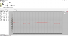
PSUD2 shows about 50mV ripple max(Peak-Peak) for the supply with 220uF=>1K=>220uF. If this is attenuated down using the factor 1:1000 it leaves about 50uV of 50Hz and its Fourier components.
If we add this to the 120uV self noise, calculated earlier i came to 170uV. And that's the upper bound of my estimate, if you build the CCS and tubes separate from the noisy rectifier.
And if all else fails you can UP the RC to 10K. and still have enough voltage to get the 85A2 to start on LOW line conditions at an operating current of 5mA
This is using Common, CHEAP parts that anyone can build.
Oh and i'd love to hear the preliminary noise specifications of your product. Before OP puts all his eggs in one basket.
Furthermore. Whats the point in trying to go any lower than this €10 BOM will give you?
Even if the circuit produces a Whopping millivolt of noise, that noise is going to go into a tube with a mu of say: 5 leaving 5mV of noise+hum at the anode. And this is stepped down by a factor of approx 30 if we calculate with a 8K:8R ratio. That leaves 5mV/30 = 150uV at the speaker terminals. Which almost a order of magnitude lower than what is commonly accepted as "Audible"
Attachments
Last edited:
If the prospect of the highest quality choice is making you nervous, better go over to ebay, or the radio-rallies.
The point is: with 845 (among others) the choice is wide, and the risk of being stuck without comparable power tubes is zero.
The point is: with 845 (among others) the choice is wide, and the risk of being stuck without comparable power tubes is zero.
Can't comment on the other stuff but,
>Other cold cathode stabilisers come nowhere near the 85A2, and no tubes of this kind are in current production. If the supply runs out - no substitutes are likely be available.
Won't we run out of GM70 wayyy before we run out of 85A2? Those little glow tubes seem to last forever while the GM70 wears out after some thousands of hours
There was a Thread on Gloeidraad.nl which mentioned that the 85A2 has a design life of about 100.000 Hours. Even if you have to resort to used pulls with 10% of life left. Those tubes will last you between 5 and 10 pairs of GM70 At which point OP will have 10K hours on a single amplifier.
Oh and the Second source for the 85A2 is OG3 or 5651? from the top of my head. Id say by the time all the good 85A2 are used up tube amplifiers will be outlawed anyway.
Last edited:
If the prospect of the highest quality choice is making you nervous, better go over to ebay, or the radio-rallies.
The point is: with 845 (among others) the choice is wide, and the risk of being stuck without comparable power tubes is zero.
What value and PN output divider resistors will your product use? I know a few Price on request part numbers that have lower self noise than the 0.8PPM inherent in the 85A2
If the prospect of the highest quality choice is making you nervous, better go over to ebay, or the radio-rallies.
The point is: with 845 (among others) the choice is wide, and the risk of being stuck without comparable power tubes is zero.
Haha don't worry, once I got it working I'm simply going to stock up on tubes to last me a lifetime. Thomas Mayer, Monolith, and similar goodies will probably be forever out of my budget but like you said, plenty of cheap stuff to be had at radiomarkets.
> The Cascode current source is going to have an Impedance in excess of 1MOhm
So you're going to aim a high-Z CCS into a passive 450Ω shunt stabiliser, connect long wires to it (terminated in a very high impedance), mount it on a board next to a bridge of diodes, and still expect microvolt-region of mains artefacts? You're not for real.
You have also omitted to deal with the problem of the bias voltage being too high, and not adjustable. The extra resistors to deal with this will raise the impedance yet more...
> Whats the point in trying to go any lower than this €10 BOM will give you?
With just the quickest look at that:
10M45 x2 and 2x DN2540 and the budget is 70% burned already.
You still need 2 PCBs, 220µF/400V extra part to try to deal with the ripple, tube sockets, caps, diodes, connectors, trimmer --- and these wondrous low noise cold cathode tubes.
10.00 in any currency is not for real - the parts budget is in even more trouble than the noise budget.
You appear to be overpromising on all fronts
> The Cascode current source is going to have an Impedance in excess of 1MOhm
So you're going to aim a high-Z CCS into a passive 450Ω shunt stabiliser, connect long wires to it (terminated in a very high impedance), mount it on a board next to a bridge of diodes, and still expect microvolt-region of mains artefacts? You're not for real.
You have also omitted to deal with the problem of the bias voltage being too high, and not adjustable. The extra resistors to deal with this will raise the impedance yet more...
If i were to make a board for this, i'd keep the PCB with rectifier and CRC separate from the CCS and two stabilizers. Just design a single panelized board that you can break in two.
I'd hook up a 22K wirewound pot on the output of the stabilizers whit 22K in series to ground, This ought to provide low impedance enough and allow for -85 to about -170V adjustment range. From a schematic posted a few pages back i figured that if you use a source follower like Ale's PCB, you wouldn't use very low value of resistor otherwise you load the preceding driver stage too much. And considering you can get TO220PF devices like the 2SK3554 with 10pF capacitance between source and drain. Miller isn't gonna ruin your day anytime soon yet.
The entire idea of the GM70 without too much in the way of cathode regeneration.. I wouldn't do it that way personally. I'd drop 50V in a 470R cathode resistor for safety, in that way there is a smaller chance of damage if anything goes wrong, and the circuit is less susceptible variation in the parameters of the output tube.
You are also omitting that if OP builds two channels of SE, OP will need to purchase at least two of your regulator boards for a stereo set if he wants to set the bias individually. Which considering you sell these as tested finished modules, if gonna be a hell of a lot more expensive than a free board design and a run of JLCPCB PCB's.
Oh and least we forget, These tubes unless you hit them with a sledgehammer fail OPEN in a shunt configuration or fail to ignite at all at end-of-life. Meaning that if anything goes wrong the output tubes will be biased in cut-off.
If you build a shunt out of solid state, and something goes wrong in the control part, it pulls down the bias supply. Same for series topologies. Because any solid state device is more likely to become conductive in catastrophic failures than fail open circuit.
Oh and that €10 figure, i put that there cause i know you would jump at that. 😛 I suspect 25-30 Euro would be a more accurate estimate.
- Home
- Amplifiers
- Tubes / Valves
- Interesting GM70 scheme... Some questions on the PSU, who helps me please?