And i'm just trying to make sure you wont use some black box that is single source.
If i may quote ROD from one of the other threads "My peeve with Florick (the OP), apart from clumsy attacks on my designs - is that he is abusing the forum to try to gain advantage"
If you need a solid state solution the TL783 may be right up your alley, however you need some external components like a transistor and a Zener to get the working voltage you need. It wont be as reliable or simple as a simple as a gas regulator tube. But you wont turn the amplifier into a christmass tree of neon regulator tubes.
Last edited:
>>>But you wont turn the amplifier into a christmass tree of neon regulator tubes.
Implying that's a bad thing 😀 At least it is a lot safer than using mercury rectifiers for glowy stuff
Implying that's a bad thing 😀 At least it is a lot safer than using mercury rectifiers for glowy stuff
Just need a schematic! 😀
Yes, let's do something constructive.
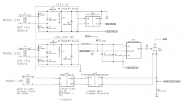
This schematic updates the previous one, to include agreed updates:
- Add Follower;
- Add +50V supply for follower: This can also use the same doubler board as the negative supply, to keep it small and neat.
- Transformer winding voltages added. The bias windings and the driver heater supply can be wound on one core; but GM70 filament supply should be the separate Antek Screened Toroids - or Audio grade screened toroids from Canterbury Windings, Air-Link, or Toroidy.pl
Enjoy!
Attachments
Rod, like Joe Cocker Said, you are so wonderful!!!Yes, let's do something constructive.
This schematic updates the previous one, to include agreed updates:
- Add Follower;
- Add +50V supply for follower: This can also use the same doubler board as the negative supply, to keep it small and neat.
- Transformer winding voltages added. The bias windings and the driver heater supply can be wound on one core; but GM70 filament supply should be the separate Antek Screened Toroids - or Audio grade screened toroids from Canterbury Windings, Air-Link, or Toroidy.pl
Enjoy!
Elena appreciates the SF power supply! 😀

Yes, let's do something constructive.
This schematic updates the previous one, to include agreed updates:
- Add Follower;
- Add +50V supply for follower: This can also use the same doubler board as the negative supply, to keep it small and neat.
- Transformer winding voltages added. The bias windings and the driver heater supply can be wound on one core; but GM70 filament supply should be the separate Antek Screened Toroids - or Audio grade screened toroids from Canterbury Windings, Air-Link, or Toroidy.pl
Enjoy!
Nicely drawn, And im glad to see that some of my suggestions didnt fall on deaf ears. I would use a gas regulator for the bias supply, As the follower PCB has a 1MEG resistor for setting the bias anyway so source impedance is less of a concern. I think you can get comparable performance by using the 0A2 shunt for the bias supply. Its noise in and of itself is no-were close to your product. however because the source follower hardly loads the thing you can RC filter the pot. I suggest a simple 10K pot from the -150V with a 10K resistor to ground. 1Meg over the wiper to -150V and a 10uf MKP from wiper to ground.
Yes, let's do something constructive.
This schematic updates the previous one, to include agreed updates:
- Add Follower;
- Add +50V supply for follower: This can also use the same doubler board as the negative supply, to keep it small and neat.
- Transformer winding voltages added. The bias windings and the driver heater supply can be wound on one core; but GM70 filament supply should be the separate Antek Screened Toroids - or Audio grade screened toroids from Canterbury Windings, Air-Link, or Toroidy.pl
Enjoy!
Thank you Rod! And apologies for the radio silence, work has pulled me away quite a bit. This is , of course, per channel, and you've expressed your preference for 2X Antek 2200 - would there be any down side to having these others would with dual secondaries to save space or even one per channel with their respective 90V and 24V secondaries?
And just to confirm no one is currently printing this HV Doubler ? I may have the PCBs printed in that case, if anyone needs some!
Perhaps I'am understanding wrong, but you need just 1 transformer -per section- for both channelsThank you Rod! And apologies for the radio silence, work has pulled me away quite a bit. This is , of course, per channel, and you've expressed your preference for 2X Antek 2200 - would there be any down side to having these others would with dual secondaries to save space or even one per channel with their respective 90V and 24V secondaries?
And just to confirm no one is currently printing this HV Doubler ? I may have the PCBs printed in that case, if anyone needs some!
> Perhaps I'am understanding wrong, but you need just 1 transformer -per section- for both channels
The drawing is for one channel, I assumed that monoblocks would be constructed.
For stereo amplifiers, The windings for bias (90Vrms 300mA and 24V rms 300mA) can be shared, but for stereo the rating should be increased to 400-600mA rms. The doubler allows lower voltage windings, but the rms current increases to about 90-100mA per channel. Rectified DC supplies need to be de-rated, to account for the peak currents (crest factor).
But in all cases, the Toroid for the filament should be separate transformer, for best performance.
> And just to confirm no one is currently printing this HV Doubler ?
I do have a stock of these, and the parts - they went out as optional kits with the previous bias regulator version.
Time to walk the walk.
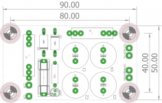
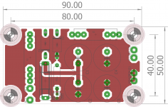
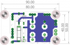
I made you a little 90x50mm board for the capacitor multiplier supplies. I added a universal footprint for a wire wound resistor in series with the AC cause this increases capacitor life.
I also added a RED 5MM LED so you can see there is charge remaining in the capacitor.
Capacitor footprint is 7.5mm pitch 18mm Diameter from the top of my head.
You can get 10 of these from JLCPCB for about 5USD( €4 )before shipping in any colour of the rainbow. If you order below 22US you likely wont have to deal with customs tax. They offer ENIG-ROHS for about 10 Euro more, that gets you nice gold over nickel plated solder pads.
DHL takes about 9 working days between ordering and delivery for me.
Order here: PCB Prototype & PCB Fabrication Manufacturer - JLCPCB
You can order as many as you like. If you also need a board for the bias supply just ask and i will upload the Gerbers here.
Attachments

Last edited:
> Perhaps I'am understanding wrong, but you need just 1 transformer -per section- for both channels
The drawing is for one channel, I assumed that monoblocks would be constructed.
For stereo amplifiers, The windings for bias (90Vrms 300mA and 24V rms 300mA) can be shared, but for stereo the rating should be increased to 400-600mA rms. The doubler allows lower voltage windings, but the rms current increases to about 90-100mA per channel. Rectified DC supplies need to be de-rated, to account for the peak currents (crest factor).
But in all cases, the Toroid for the filament should be separate transformer, for best performance.
.
Yes, of course, double the current capacity of transformers.
No monoblocks, we've here two cases, one power psu, other one for music.
So to wrap up,
One transformer is for b+ of both gm70 (800V, 0.4A) and b+ of both driver tubes (280V, 0.1A) ,
One for bias -250V (90V, 600mA, +50V (24V, 600mA), and 6.3v (8V, 3A) for drivers filaments,
One for gm70 filaments (2*20V, 8A) through your regulators.
I have measured the bias of 4 GM70 tubes (Vak should be around 1060v - I measured my B+ years ago, I don't think it has changed much since).
Copper1 @90mA: -99v @80mA: -104v
Copper2 @90mA: -106v @80mA: -111v
Graphite1 @90mA: -96v @80mA: -102v
Graphite2 @90mA: -99v @80mA: -105v
Copper1 @90mA: -99v @80mA: -104v
Copper2 @90mA: -106v @80mA: -111v
Graphite1 @90mA: -96v @80mA: -102v
Graphite2 @90mA: -99v @80mA: -105v
Last edited:
Thank you for the measurements Vincent -
For those who have worked with HT projects like this - what, if any, disconnects /connectors could be used for high tension umbilical? I did find one mil-spec which is non-locking it seems, but I can't imagine it would be practical to have the umbilical permanently attached...?
All thoughts welcome here!
César
Lemo makes nice connectors for the 1KV. I would build that separately and feed it through a separate high voltage coax. And only join the ground at the star point in the amplifier itself.
Another option is high voltage BNC BNC HT / MHV High Voltage Connector | Radiall
Another option is high voltage BNC BNC HT / MHV High Voltage Connector | Radiall
- Home
- Amplifiers
- Tubes / Valves
- Interesting GM70 scheme... Some questions on the PSU, who helps me please?