2019 version had change some relay control byte and DAC channel, and these parameter store in ads7871_v3s.ini. Previous versions of ini files may not work with 2019 version.Hi,
now that´s weird. 😕
Started the tracer today again and it worked!
Iirc the only difference I remember could have been that I started the ´ADS8771_v3.exe´ from the folder I downloaded from gerhard (#194) instead of the original ´Locky_z Curve Tracer Software - v3.5.zip´.
Got some nice curves and some very distorted which I think is due to some unfortunate settings of Vb et al.
So I closed the app and restarted it .... guess what ... no sweep but just a single measurement. 🙁
Closed and restarted the App again and it worked again 😕
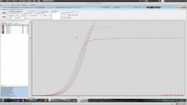
Well, so far I´m not too familiar with all the settings .... so I get results which sometimes appear reasonable and sometimes odd (especially the Hfe-Ic curves didn´t show sensible values ... a BC547C with a Hfe of >10.000 or <50??)
Here are the screen shots (btw. what and where is that ´save-file´?
1st: Options/System | 2nd: Diagnose/Device Test | 3rd: Measurement/Load Conditions/NPN-Hfe-Ic default | 4th: same, but parameters adjusted for BC547C | 5th: Go!, with and without Calibration
jauu
Calvin
Suggestions go to Curve-Tracer/2019/ENG/EXE at master * locky-z/Curve-Tracer * GitHub, download the ini file for 2019 version.
Your last picture shows a very large hfe, I think the reason is the incorrect relay control bit in the ini file,
Got some nice curves and some very distorted which I think is due to some unfortunate settings of Vb et al.
So I closed the app and restarted it .... guess what ... no sweep but just a single measurement. 🙁
Closed and restarted the App again and it worked again 😕
..
Well, so far I´m not too familiar with all the settings .... so I get results which sometimes appear reasonable and sometimes odd (especially the Hfe-Ic curves didn´t show sensible values ... a BC547C with a Hfe of >10.000 or <50??)
I never got meaningful results from bipolar transistors. Methinks the DUT then just
oscillates and you get random numbers. I did not investigate this because I happened
to get somewhat usable results for the FETs I was interested in, and that removed the
pressure. Absolutely no interest to debug someone else's hardware. Simply using
base stoppers would distort the results.
FETs are also not free from hickups, see the current limit effect on some DUTs in
the picture. Measured again, preferably with a different moon phase, these FETs behaved
normally.
And I don't miss the documented raw interface as long as I cannot set up the thing
from the intended surface without leaving doubt because of the "documentation".
When I'm going to program myself, I can just as well use lab supplies / fun generator /
scope under GPIB control.
What I wanted was: switch it on, plug the DUT in and see the results. 😡
Gerhard
Attachments
Last edited:
Hi,
I installed the files and the tracer is running.
Am getting mostly weirdo results when running the scripts or predefined measurements. 🙁
So far a rather disappointing experience since the documantation leaves room for improvement (No technical specs .... am I right that the maximum supply specs are +40V and 3.2A?)
jauu
Calvin
I used the power supply of a slaughtered HP inkjet pro : 32V / 3.5A
It was a little bit less voltage than the max allowed, so you are probably right.
I can't find the requirements right now. It should be enough for my +-5V world.
Try some slowish FETs first.
Gerhard
It was a little bit less voltage than the max allowed, so you are probably right.
I can't find the requirements right now. It should be enough for my +-5V world.
Try some slowish FETs first.
Gerhard
Last edited:
1. Make sure the ADs7871_vs.ini is downloaded from Github.Hi,
I installed the files and the tracer is running.
Am getting mostly weirdo results when running the scripts or predefined measurements. 🙁
So far a rather disappointing experience since the documantation leaves room for improvement (No technical specs .... am I right that the maximum supply specs are +40V and 3.2A?)
jauu
Calvin
2. Load the measurement conditions of "Ic-hfe" or "Vgs-ID" or "Vbe-Ic" with "fix Vce".
3. Make sure the being test component is good and you sure know their pin number. If the test component is broken, the curve is incomprehensible.
4.The measurement condition that does not have "Fix Vce" is "Customs Mode", which may need to be based on your supply voltage, may do some adjust.
The 2019 version sell on ebay.
Locky_z 2019 Curve tracer | eBay
Locky_z 2019 Curve tracer with new component | eBay
For the disassembled version, what are the steps to complete tester ?
The curve tracer are assembled. Just need a 32-40V power supply and a PC run with this software. The software can download from github.For the disassembled version, what are the steps to complete tester ?
So you confirm that the difference between $179 disassembled product and $219 complete tester is only power supply ?The curve tracer are assembled. Just need a 32-40V power supply
So you confirm that the difference between $179 disassembled product and $219 complete tester is only power supply ?
Just my 2 cents, but what I think he means with partially disassembled components is that some components are re-used parts from other equipment, not that you have to assemble the unit yourself.
AnalogJoe right.
$179 and $219 just the component difference. but they all are completed and test pass.
$179 use some "re-used" component, such as relay/power transistor/capacitor/DAC.
$219 use new component.
$179 and $219 just the component difference. but they all are completed and test pass.
$179 use some "re-used" component, such as relay/power transistor/capacitor/DAC.
$219 use new component.
thanks AnalogJoe for answer.
locky_z : it is not clear in listing as well as your answer here. Now I made my mind 😎
locky_z : it is not clear in listing as well as your answer here. Now I made my mind 😎
One of my best buy, I used this great curve tracer all the time. A must buy for anyone interested in matching. Very recommended...
I just bought one on e-bay.
For a curve tracer I use a programmable PSU and a bench multimeter both with GPIB and in MATLAB I automate everything to get the I-V curves, it works but its not as straightforward, I'm hoping this new curve tracer will substitute my current setup.
For a curve tracer I use a programmable PSU and a bench multimeter both with GPIB and in MATLAB I automate everything to get the I-V curves, it works but its not as straightforward, I'm hoping this new curve tracer will substitute my current setup.
In fact, I didn't found much recent models with printing options (locky_z, changpuak...)
Arduino/Genuino Shield ''TANACHAI'' aka Transistor Curve Tracer
and among restricted choice, choose one with good feedbacks !
Arduino/Genuino Shield ''TANACHAI'' aka Transistor Curve Tracer
and among restricted choice, choose one with good feedbacks !
Thank you for the link. A max current of 150mA is significantly better than the Peak Atlas DCA75 which is limited to 12mA. Of course the LockyZ goes up to 3 amperes but some people prefer to avoid it for software compatibility reasons.
The DCA75 is useless for serious curve tracing in power amps, perhaps for small signal it is ok.
What are specs for non useless curve traceing in power amps?The DCA75 is useless for serious curve tracing in power amps, perhaps for small signal it is ok.
- Home
- Vendor's Bazaar
- Intelligent Curve Tracer 3.0 release