No, the zeners and transistors are not in the LTspice deliverable.
But there are similar ones, it just needs a bit of time to select them.
Jan
But there are similar ones, it just needs a bit of time to select them.
Jan
I'm sorry it's been two years since I don't use LTS. Last time I did, I did not have any problems with uploading the files.
Will use my latest LTS version and replace all diodes and transistors on my asc files.
Will use my latest LTS version and replace all diodes and transistors on my asc files.
If you use parts selected from the original LTspice install, that'll work for anyone.
If you use 3rd party parts you import yourself like the pass transistor and the zeners, than you need to do either of two things if you want anyone to run it.
1 - place those non-LTspice model files on the schematic, or 2 - include their .lib model files with the schematic in the upload. Or zip it all and post that.
Jan
Ok, I will upload my files zipped, including txt model files in it. Now the Spice directive can be .inc or .lib.If you use parts selected from the original LTspice install, that'll work for anyone.
If you use 3rd party parts you import yourself like the pass transistor and the zeners, than you need to do either of two things if you want anyone to run it.
1 - place those non-LTspice model files on the schematic, or 2 - include their .lib model files with the schematic in the upload. Or zip it all and post that.
Jan
I am more familiar with the .inc directive, so that's the one I will use. Would that be fine?
Hi all.
Do someone know where to get ultrafast rectifier diodes? I have some but when using them the LLC smps do not work right, it does only for now with schottky diodes. Ultrafast recovery diodes I have also, smae problem, the output voltage is just half and feedback does not work.
THanks in advance for help finding right diode models.
Attachments
I found this in one of my directories, it was datestamped 2019. I have no idea how (in)accurate this simulated diode is, compared to the real thing in the real world. Caveat Emptor.
You will note that it is similar to this model found on Vishay's website.
Code:
.MODEL UF4007 D ikf=0.15 N=3.97671 IS=3.28772u RS=0.149734
+  EG=1.11 XTI=3 CJO=2.92655E-011 VJ=0.851862 M=0.334552
+  FC=0.5 TT=1.84973E-007 BV=1000 IBV=0.2 Iave=1 Vpk=1000
+  type=silicon
You will note that it is similar to this model found on Vishay's website.
Last edited:
Thanks for the supply. I have also found a bunch of these diodes in the standart.dio but some do not work well, I get much to low output voltage. Yours do well. Thanks.I found this in one of my directories, it was datestamped 2019. I have no idea how (in)accurate this simulated diode is, compared to the real thing in the real world. Caveat Emptor.
Code:.MODEL UF4007 D ikf=0.15 N=3.97671 IS=3.28772u RS=0.149734 + EG=1.11 XTI=3 CJO=2.92655E-011 VJ=0.851862 M=0.334552 + FC=0.5 TT=1.84973E-007 BV=1000 IBV=0.2 Iave=1 Vpk=1000 + type=silicon
You will note that it is similar to this model found on Vishay's website.
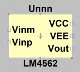

The built-in opamp2.asy symbol can be used for most LM4562 spice models as long as the model matches the usual pin order for op amps -- there really is no need to create a special symbol file for the LM4562.
Attached is the original National Semiconductor model for the LM4562. I've found this one to be better than later ones issued by Texas Instruments, which acquired National Semiconductor back in 2011.
Attached is the original National Semiconductor model for the LM4562. I've found this one to be better than later ones issued by Texas Instruments, which acquired National Semiconductor back in 2011.
Attachments
I just realized that I uploaded a version of the National Semiconductor model that I had modified for my own use. The only difference from the original is the renaming of the nodes for the external pins in the model itself, to match the "1 2 3 4 5" order in the model definition. This was purely an aesthetic thing (yeah, I'm like that sometimes).
Attached is the true original (unmodified) National Semiconductor LM4562 model. Sorry for the confusion.
Attached is the true original (unmodified) National Semiconductor LM4562 model. Sorry for the confusion.
Attachments
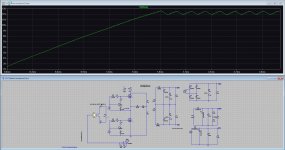
Simplest of circuits, and I can't get the correct answers in simulation.
Domestic mains supply, set at 240 volts rms. Typical resistance of a 100A fuse is around 0.00073 ohms. It all fell apart when I tried adding a similar low value as supply cable resistance.
I can not get the correct voltages across the two low value resistors. They are in series and I get different voltages across each. Have tried running the sim with a correct timestep like we would with audio circuits and I still get crazy results. 4 volts rms across the first 0.00073 ohm is 5.5kA
The second image is set as a DC sim and the results are correct.
What do I need to do to get it to calculate correctly?
Attachments
The mystery remains why does the maximum timestep value determine how AC voltages are calculated ???
Just trying it over 1 cycle with no timestep.
.tran 0 20ms 0
Node 1 = 241.12v
Node 2 = 241.07v
Node 3 = 241.02v
Hmmm...
Edit... even one half cycle works (.tran 0 10ms 0)
.tran 0 20ms 0
Node 1 = 241.12v
Node 2 = 241.07v
Node 3 = 241.02v
Hmmm...
Edit... even one half cycle works (.tran 0 10ms 0)
Calculate the percentage error
- 100% * ( (LTSPICE answer) - (correct answer) ) / (correct answer)
As originally set up the error for the voltage across R1 is 8411% in error. Using a calculator I get 0.04864 vrms across R1 and the same across the fuse. LTspice gets 4.14
Edit... 4.14 across R1. LTspice gets a totally different result for the fuse which is odd as it is a series circuit.
Edit... 4.14 across R1. LTspice gets a totally different result for the fuse which is odd as it is a series circuit.
Hmm, I calculate V(node1) = 341/sqrt(2) = 241.123V whereas image1 of #3372 says V(node1) = 239.52V ; giving an LTSPICE error of -0.664%
Then I calculate the resistance between node3 and GND is 3.61708 ohms. Which means that V1 drives a load resistance of 3.61854 ohms, so the voltage at node2 is (341/sqrt(2)) * (1 - (0.00073 / 3.61854)) , namely , 241.075V
whereas image1 of #3372 says V(node2) = 235.38V ; giving an LTSPICE error of -2.362% . That's unacceptably high so you probably want to increase the number of datapoints LTSPICE uses to calculate its RMS average. .OPTIONS MAXSTEP is one easy way.
- Home
- Design & Build
- Software Tools
- Installing and using LTspice IV (now including LTXVII), From beginner to advanced