Thanks Mark. I worked through all those numbers on a bit of paper as well 🙂 The sky high percentage error is seen when you look at the voltage across the resistor. The current would calculate at around 5.5kA 😱
Can someone tell me what else can I simulate on an audio circuit, specifically a phono preamp, besides PSSR, Noise and Frequency Response that is important to know?
For instance, is there a way to simulate the dynamic range of a preamp?
For instance, is there a way to simulate the dynamic range of a preamp?
Not sure if it has been mentioned anywhere but I spotted this on the latest installer of LTspice XV11. I was doing an install on an old laptop and gave it a whirl. A quick install for sure. Haven't really tried it beyond the most basic stuff. I couldn't just find where the program lives after install either which is a bit odd unless it added to the existing install. Bit of a mystery is that.
The installer is here for anyone interested. Based on my experience if you open the link then it will immediately launch the installer, it is NOT a page about the new version. Copy and paste the code below if you want it.

The installer is here for anyone interested. Based on my experience if you open the link then it will immediately launch the installer, it is NOT a page about the new version. Copy and paste the code below if you want it.
https://LTspice.analog.com/download/latest/LTspice64.msi
NB: this link above might be for the stable version - EDIT: or maybe not since it does display the changes log....
After Sync Release, you can go to Help and find a link to the beta in the contents column's Beta Release item. subdir has the beta version in the link.
After Sync Release, you can go to Help and find a link to the beta in the contents column's Beta Release item. subdir has the beta version in the link.
This is the 17.1.5 beta version. I downloaded the beta from within the 17.0.36.0 stable release Help link and did a file compare with this version; they are identical. The digital signature in the installer file is dated October 31, 2022.
Thanks folks. I've not put this on my main system as yet (at this point I may or may not do so) as I want to try and figure out how this new version all fits together.
According to the beta documentation, it can be installed on the same PC as the released version without conflict. It is a completely separate installation from the stable release version so it is probably safe to install (although I myself will probably wait until the actual release of version 17.1).
Thanks Ray. I had a bit more of a play earlier and one advantage (I think) is that by storing the user files in %localappdata% directories means that they are not indexed (again I think that is what will happen). If so then that could be advantageous to making and restoring disk images because the index file is not recommended to be included in a backup and programs such as Macrium automatically exclude the index file. That means a quick restore actually takes a long time to fully complete after the restore has finished as Windows has to reindex all those LT small files.
Interesting. One to watch I think rather than jump in and use the new version exclusively.
Interesting. One to watch I think rather than jump in and use the new version exclusively.
The pin names are just for your prsonal convenience, you can change them to anything you like with no difference in electrical behaviour.Please forgive my ignorance, but I am adapting the LM4562 model to LTSpice, using the datasheet and all, and these are the pins that I get for using. Which are the +In an -In pins? I have never seen Vinm and Vinp.
What matters is the order of the pins in the model, that must correspond to the order they were placed in the symbol.
For instance, you often see models that start with the following:
*pins: Vcc Vee Vout Vin
.model x 1 2 3 4
. ..........
Then if you auto-create the symbol with LTspice which is what you'd normally do, the symbol will have the pins 1 2 3 and 4. From the above, you know that they really are the Vcc, Vee, Vout and Vi pins of the model as well as the real thing.
So you can right click the numbers in the symbol and rename them to Vcc Vee Vo Vi if you want, or to thisispos, thatstheother, wow and Vin and the operation of the model in a circuit will not change.
The order is important, not the name.* And don't forget to save the symbol after modification!
Jan
*If you look through the text of the model you will see that nodes 1, 2, 3 and 4 are used in many places, where those pins connect to the R's and C's etc of the model circuitry. This is no different than any normal LTspice circuit.
Dear forum users,
For a school project i am designing a tube amplifier.
To do some simulatios, I am using LTspice.
But now i get this error, "Undefined subcircuit: triode"
I am using the standard triode model, and this is my model .lib
.SUBCKT ECC83 1 2 3 ; P G C; (Triode)
Mullard data sheet 1970 AKA 12AX7A 7025
library format: LTSpice 31-May-2008
X1 1 2 3 TRIODE MU=98.11 EX=1.459 KG1=1734.7 KP=754.39 KVB=119.9 VCT=0.50 RGI=2000 CCG=2.3p CGP=2.4p CCP=0.9p ;
.ENDS ECC83

Does anyone know what I am doing wrong?
For a school project i am designing a tube amplifier.
To do some simulatios, I am using LTspice.
But now i get this error, "Undefined subcircuit: triode"
I am using the standard triode model, and this is my model .lib
.SUBCKT ECC83 1 2 3 ; P G C; (Triode)
Mullard data sheet 1970 AKA 12AX7A 7025
library format: LTSpice 31-May-2008
X1 1 2 3 TRIODE MU=98.11 EX=1.459 KG1=1734.7 KP=754.39 KVB=119.9 VCT=0.50 RGI=2000 CCG=2.3p CGP=2.4p CCP=0.9p ;
.ENDS ECC83
Does anyone know what I am doing wrong?
This looks like the Norman Koren model. Individual triode models (like for the ECC83) are specified with parameters that apply to a generic model, in this case a model named "TRIODE."
Try this ECC83 model instead. It includes the generic TRIODE model as well as the parameters for the ECC83. It also include the DX model required by the generic TRIODE model.
Try this ECC83 model instead. It includes the generic TRIODE model as well as the parameters for the ECC83. It also include the DX model required by the generic TRIODE model.
Code:
.SUBCKT ECC83 1 2 3 ; P G C; (Triode)
* Mullard data sheet 1970 AKA 12AX7A 7025
* library format: LTSpice 31-May-2008
X1 1 2 3 TRIODE MU=98.11 EX=1.459 KG1=1734.7 KP=754.39 KVB=119.9 VCT=0.50 RGI=2000 CCG=2.3p CGP=2.4p CCP=0.9p ;
.ENDS ECC83
******************
.SUBCKT TRIODE 1 2 3 ; A G C
E1 7 0 VALUE={V(1,3)/KP*LOG(1+EXP(KP*(1/MU+(V(2,3)+VCT)/SQRT(KVB+V(1,3)*V(1,3)))))}
RE1 7 0 1G
G1 1 3 VALUE={(PWR(V(7,0),EX)+PWRS(V(7,0),EX))/KG1}
RCP 1 3 1G ; TO AVOID FLOATING NODES IN MU-FOLLOWER
C1 2 3 {CCG} ; CATHODE-GRID
C2 2 1 {CGP} ; GRID=PLATE
C3 1 3 {CCP} ; CATHODE-PLATE
D3 5 3 DX ; FOR GRID CURRENT
R1 2 5 {RGI} ; FOR GRID CURRENT
.ENDS TRIODE
******************
.MODEL DX D(IS=1N RS=1 CJO=10PF TT=1N) ; diode used by the Triode, Pentode Beam Tetrode models
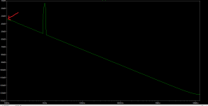
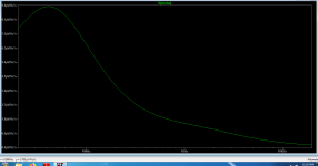
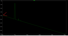
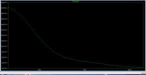
******************Hi guys! There's something I don't understand about LTspice noise simulations.If I perform the .noise command and a fft on the same circuit i get two results.I always thought that the FFT baseline represents the noise of the circuit, but that doesn't correlate with the noise density result from the .noise command in a circuit where I should get the lower noise where the .noise command returns me the higher noise density throughout all the adio band. Those two circuits have exactly identical input source and output load , and identical input and output signal amplitudes.Can someone explain what the baseline in the fft graph shows?
Attachments
Maybe a stupid question, but I can't seem to find the way to do a distortion versus level sim.
Anyone can give me a pointer?
Jan
Anyone can give me a pointer?
Jan
I usually step the level of a .four sim and look at the log file (or copy it into a speadsheet -- or extract the values with a script -- and plot it from there). If you have any time constants in the circuit (like RC highpass etc) you need to run the sim for enough cycles for the time constants to fully settle, otherwise the results will be skewed. Time step also needs some thought to avoid errors.Maybe a stupid question, but I can't seem to find the way to do a distortion versus level sim.
Anyone can give me a pointer?
Jan
Perhaps not what you have in mind, though.
Well, I was hoping that I could directly graph it, but that may not be possible.
Graphing it separately is possible of course but basically being a lazy person I would hope LTspice would do it for me ...
Jan
Graphing it separately is possible of course but basically being a lazy person I would hope LTspice would do it for me ...
Jan
- Home
- Design & Build
- Software Tools
- Installing and using LTspice IV (now including LTXVII), From beginner to advanced