A Fourier analysis of the voltage is certainly the usual way to do it. I had done it with current through the load because your original circuit did this and I assumed there was a reason for your doing it this way.
I've attached your file again with an additional Fourier analysis of the voltage across the load. Note that the current and voltage waveforms are exactly in phase, and that the results of the two .four analyses are identical, which is exactly what one would expect with a resistive load.
As an aside, it is interesting to see what happens if one substitutes a loudspeaker equivalent circuit for the resistive load in the simulation, and I have done this in the zipped folder. The two analyses now have different results, the current and voltage waveforms are not aligned in time, and the question arises: which result more accurately reflects what we actually hear?
The results are: THD_voltage = 0.068%; THD_current = 0.26%.
This question arose in a recent thread in the Tubes forum, "Do tubes actually sound like anything?", especially from post #152 onwards. But I didn't dare go near that thread...
Thank you @Ludus Tonalis, why I did the current measurement is because it was a btl amp, en measuring only one half does give not the effect of this, maybe it does with two resistors and measure on the midle of them.
Now I now how that ,four works, thanks.
kees
Last edited:
Does anybody have a model template for a center-tapped inductor or know how best to make one?
I built one using two inductors and the directive "K1 L1 L2 1" but the resulting model doesn't behave like a dual winding choke. Any suggestions for a way to create it? I'd like to model the Lundahl LL1685.
Thanks !
Wouldn't you just make L1 and L2 and tie the undotted end of L1 to the dotted end of L2?
Then connect the other ends to your circuit.
tommost
Hi all
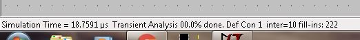
What means deffcon in ltspice, when this happens I get a strange run in nS I think oscillation is the case here?
I get also no currents, nowhere only voltages when i do alternate, then it does run, but strange because voltages
are present the jef has to let see current, it has seen the voltages who do work properly.
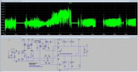
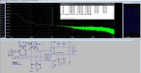
pic fft is output chaos, it is not the first time i get trouble with the 64 bit version of LTspice, but maybe I do something wrong, this amp did work a while ago, and did nothing to change parts, so it has still have to work properly, so maybe something to learn here.
thanks
What means deffcon in ltspice, when this happens I get a strange run in nS I think oscillation is the case here?
I get also no currents, nowhere only voltages when i do alternate, then it does run, but strange because voltages
are present the jef has to let see current, it has seen the voltages who do work properly.
pic fft is output chaos, it is not the first time i get trouble with the 64 bit version of LTspice, but maybe I do something wrong, this amp did work a while ago, and did nothing to change parts, so it has still have to work properly, so maybe something to learn here.
thanks
Attachments
Last edited:
Hi all
What means deffcon in ltspice, when this happens I get a strange run in nS I think oscillation is the case here?
I get also no currents, nowhere only voltages when i do alternate, then it does run, but strange because voltages
are present the jef has to let see current, it has seen the voltages who do work properly.
pic fft is output chaos, it is not the first time i get trouble with the 64 bit version of LTspice, but maybe I do something wrong, this amp did work a while ago, and did nothing to change parts, so it has still have to work properly, so maybe something to learn here.
thanks
Defcon means the simulation is having trouble converging, that's why it slows down. It can be caused by many factors, often due to bad models.
tommost
Wel I have discover that when I do reset to default, it works again, so the set to gear, or alternat whataver can be give trouble.
Thw writer of this program did use defcon name he did read from the militairy? cute hehe, happenly he did not program a atomic bomb in it.
regards and thanks for help.
Thw writer of this program did use defcon name he did read from the militairy? cute hehe, happenly he did not program a atomic bomb in it.
regards and thanks for help.
Wel now I get everything wrong, I can not probe current in the transistors itselfs, only voltage.
Wel now I get everything wrong, I can not probe current in the transistors itselfs, only voltage.
Sometimes it can be hard to get the cursor away from the node voltage to the branch current, especially if the traces between components are short.
You can always run the simulation, right click on the waveform pane, select Add Traces from the dialog box, this will present you with a list of the node voltages and branch currents. Just select the one you want.
tommost
Wel I can not probe the mosfets from the library, al the other does work also the resistors and diodes.
I have never had this problem in al the years, and the circuits I mention about did always work, never problems, but after the last update, nothing does right it seems, the sk270 jfet for example from the standart models did not work anymore, no current flowing through it.
regards
I never heard of this problem, and I did LTSpice seminars for years... At this point I would uninstall and reinstall.
tommost
How is it possible to see the FFT plot for differential signals?I can make the VIEW FFT command for a differential probe signal but it's not showing anything, nor it does show in the spice error log.
How is it possible to see the FFT plot for differential signals?I can make the VIEW FFT command for a differential probe signal but it's not showing anything, nor it does show in the spice error log.
Make a behavioral voltage source (bv) equal to the difference between the 2 nodes you want to measure, label the output something you'll recall like OH_BEHAVE, and then run the simulation. Click on the waveform pane, then the View menu, then FFT, and you should see V(OH_BEHAVE) as a plottable choice.
tommost
Thank You Sir! I didn't know that .Make a behavioral voltage source (bv) equal to the difference between the 2 nodes you want to measure, label the output something you'll recall like OH_BEHAVE, and then run the simulation. Click on the waveform pane, then the View menu, then FFT, and you should see V(OH_BEHAVE) as a plottable choice.
tommost
Attachments

Thank You Sir! I didn't know that .
Glad to help. LTSPICE is a marvelously capable program. During my tenure at Linear Tech I probably did about 2 or 3 LTSPICE seminars a year (not nearly as many as Mike E or as good but still a lot) and almost every time I learned something from the seminar attendees!
tommost
How is it possible to see the FFT plot for differential signals?I can make the VIEW FFT command for a differential probe signal but it's not showing anything, nor it does show in the spice error log.
Make a behavioral voltage source (bv) equal to the difference between the 2 nodes you want to measure, label the output something you'll recall like OH_BEHAVE, and then run the simulation. Click on the waveform pane, then the View menu, then FFT, and you should see V(OH_BEHAVE) as a plottable choice.
Alternatively, just use waveform arithmetric.
Suppose you have two nodes labelled out+ and out-. Perform a .tran simulation, right click on the waveform window, click View then FFT as normal. The dialogue box "Select Waveforms to include in FFT" opens. Note that Waveforms is in the plural.
Click on V(out+) to highight and select it. Then Control-Click V(out-) to additionally highlight and select it. Both voltages should now be selected. Click on OK.
A new dialogue box "Select Visible Waveforms" opens with the two selected waveforms showing. Alt-Double-Click on either of them and the Expression Editor opens. Adjust the displayed expression so that it reads V(out+,out-) and click on OK twice to display the FFT of the edited expression.
Note that you can only include a voltage or current in the final edited expression if it was pre-selected in the first "Select Waveforms to include in FFT" dialogue box.
Nice! I never did that before. This is what I meant by learning something new about LTSPICE all the time.
One of the features that often drew "oohs and ahhs" at seminars was schematic cleanup. When drafting you can draw lines right through a component and as soon as you leave drafting mode the short will get cleaned up & disappear. A lot of people never knew that.
tommost
One of the features that often drew "oohs and ahhs" at seminars was schematic cleanup. When drafting you can draw lines right through a component and as soon as you leave drafting mode the short will get cleaned up & disappear. A lot of people never knew that.
Yes, and it works the other way round, too. If you place a component on a line that was drawn earlier, the bit of line under the component disappears.
Here's a simple line that i finally understand 🙂...Yes, and it works the other way round, too. If you place a component on a line that was drawn earlier, the bit of line under the component disappears.
Incidentally dreamth, something I forgot to mention: you can also use waveform arithmetic in your .four command without needing a behavioural voltage source. For example:
.four 20k 10 8 V(Out1,Out2)
(using your example in post #1833)
.four 20k 10 8 V(Out1,Out2)
(using your example in post #1833)
Does anybody have a model template for a center-tapped inductor or know how best to make one?
I built one using two inductors and the directive "K1 L1 L2 1" but the resulting model doesn't behave like a dual winding choke. Any suggestions for a way to create it? I'd like to model the Lundahl LL1685.
Thanks !
Wouldn't you just make L1 and L2 and tie the undotted end of L1 to the dotted end of L2?
Then connect the other ends to your circuit.
tommost
Yes, that's what I read in a how-to posted on one US University's EE website, with the directive as posted above . . . . but it doesn't yield the results that a real-world inductor does. I know, I had one in circuit on my bench.
- Home
- Design & Build
- Software Tools
- Installing and using LTspice IV (now including LTXVII), From beginner to advanced