This 'ac mode' and 'trans mode' is confusing.
A .ac is a frequency domain simulation, you look at something versus frequency on the X-axis. Like a spectrum analyzer.
A .tran is a time domain simulation, you look at something versus time on the X-axis. Like a scope.
What you do with .ac gives you the Zout versus frequency, and I guess that's what you want. Using a .trans gives you the Zout for one frequency only*, but you can see the 'shape' of the Zout related to the shape of the load current. Not sure whether that is useful.
*unless you use a multi-frequency or FM source
Jan
yes thanks. That’s what I thought, but I was getting some misleading AC mode readings without a time reference. I put a current source on the mosfet that was being used to test a voltage source per Molly’s suggestion. So I loaded the mosfet with a 3k resistor for 100mA at 300V and put a current source of 100mA sine wave between the gate and source. But the simulation gets stopped with an error.
You want to keep that error message a secret?
BTW, I don't know how your circuit looks (another secret?) but loading the regulator with 100mA DC and then pinging it with 100mA RMS won't work well. Keep the exitation current peak below the DC load current. Like 50%.
Jan
BTW, I don't know how your circuit looks (another secret?) but loading the regulator with 100mA DC and then pinging it with 100mA RMS won't work well. Keep the exitation current peak below the DC load current. Like 50%.
Jan
It’s the same power supply from the other thread. Should I- post it over there? I know we like to keep threads clean. I’ll post it tomorrow after some zz’s
I think many here who want to help are not looking forward to chase something or other up though the many 100,000's of posts here, only to hear the poster tell them: no it's not that one ...
We also have lives. Most of us, anyway ;-)
Also, a posting 'the simulation gets stopped with an error' is unlikely to lead to a specific reply/tip. Its like telling your doctor 'I don't feel well' and expect a detailed, to-the-point medication prescription.
Jan
We also have lives. Most of us, anyway ;-)
Also, a posting 'the simulation gets stopped with an error' is unlikely to lead to a specific reply/tip. Its like telling your doctor 'I don't feel well' and expect a detailed, to-the-point medication prescription.
Jan
Last edited:
For testing Zout, you don't need the M1, the 3k, whatever. Just a current source to put current into the output. Keep it as simple as possible. Get rid of that LED stuff, unnecessarily slows down the sim.
Use a realistic load resistor to draw DC current, that is representative like 50mA or 100mA.
I can't see all the stuff at the left but you don't need to drag any rectifiers along, just put a DC source at the input.
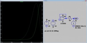
For a freq sweep do a .ac with a current source into the output, plot the current and the resulting voltage at the output, divide to get Z.
Jan
Use a realistic load resistor to draw DC current, that is representative like 50mA or 100mA.
I can't see all the stuff at the left but you don't need to drag any rectifiers along, just put a DC source at the input.
For a freq sweep do a .ac with a current source into the output, plot the current and the resulting voltage at the output, divide to get Z.
Jan
Last edited:
BTW A timestep error often results from strong non-linearity in the circuit. Things like driving a MOSFET directly with a voltage source at the gate is such a strong non-linearity.
You can though specify a manual minimum time step, see the help file.
Jan
You can though specify a manual minimum time step, see the help file.
Jan
Use a realistic load resistor to draw DC current, that is representative like 50mA or 100mA.
Jan
Do you mean a 6K resistor for 50 mA? Do I enter 50mA as the Surrent source DC offset or leave that blank.
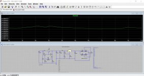
For AC I believe I'm testing correctly. Right? Picture below.
Attachments
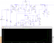
Either way. The point is that the regulator cannot sink current. So if you ping the output with an ac current to measure Zout, you must be sure that at all times there is a net current drawn from the supply. You can use a load resistor or a DC offset in the test current source, to generate a DC load current that is larger than the ac test current amplitude at the negative phase.
Jan
Jan
That’s why I had that LED and resistor in there. I guess I can just put a 6k resistor to ground to load the regulator at 50mA, right?
This 'ac mode' and 'trans mode' is confusing. <snip>
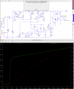
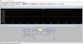
Maybe a picture helps? Showing how to used the AC-plot for impedance plotting 🙂
Note: On the left side/scale you see output impedance displayed in Ohm's
Attachments
Last edited:
The Kmultiplier is backwards, the input and output are swapped. That file won't run for anyone else because of the missing LM317 files.
Problem with LTSpice model
Hello All,
Obviously, my newbieness is showing, but I have an LTSpice subckt file entitled "vacuum.sub" (authored by Duncan Munro), and I am trying to connect some of the subcircuits in this file with the triode symbol in the LTSpice symbols directory.
I have tried opening the vacuum,sub file in LTSpice (as text), and right clicking on the name of the sub circuit, but it will only allow me to make a new behavioral symbol, and I cannot connect the 12ax7 subcircuit with the "triode.asy" file in the LTSpice symbols directory.
Can someone tell me how I can do this?
I am assuming that the tube people know what the "vacuum.sub" file is, But I can upload this file if you like (it is also on git).
Thanks,
Bob
Now , can someone help me?
I really want to know if such a psu is good enough for a class a head amp of around 200mA to 300mA.
Regards
Prasi
I really want to know if such a psu is good enough for a class a head amp of around 200mA to 300mA.
Regards
Prasi
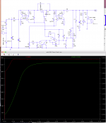
A few quick thoughts...
A 50 ohm load has been added to take account of your 200-300ma requirement.
There isn't enough voltage differential for the 317 to operate. Increase the input voltage to 25 and see how the output of the IC becomes much much cleaner.
The rectifier diodes have been swapped for Shottky types.
Edit... there is an LM317 (LT317) model already included in LTspice. Interesting difference in simulation 😉
Attachments
Thank you Mooly,
I will set it up for a 18VAC transformer and set the output voltage to 12 VDC.
Now my question is , how to estimate the output impedance through spice and also is there a way to plot noise.
LM317 model: I am wondering about the difference too. I had used the LM317 model by 'Wintermute' I think.
I will set it up for a 18VAC transformer and set the output voltage to 12 VDC.
Now my question is , how to estimate the output impedance through spice and also is there a way to plot noise.
LM317 model: I am wondering about the difference too. I had used the LM317 model by 'Wintermute' I think.
Last edited:
- Home
- Design & Build
- Software Tools
- Installing and using LTspice IV (now including LTXVII), From beginner to advanced