A simple way to find double node-names (probably this has been said bevore):
run the sim and go to the plot window. Hold the alt-key and click on the signal-name.
The node will be highlighted in the schematic- also when they are doubled.
Boris
run the sim and go to the plot window. Hold the alt-key and click on the signal-name.
The node will be highlighted in the schematic- also when they are doubled.
Boris
Hi All
I do not now but I use sub circuits, and these have nodes named inside them, is this maybe the cause.
I only can sim when I delete the copied part, as you see, nice plot, three level. If the subcircuit is cause I did
learn again something more but maybe subcircuit nodes do not impact schematic because I use also more
then one in a simple channel without that copy for BTL.
regards
Attachments
Well if LTspice sees the same names in different places it concludes you want those nodes connected. It's not an LTspice bug.
That said, I do not know if LTspice considers labels in sub circuits as local. If so, that should work.
Jan
That said, I do not know if LTspice considers labels in sub circuits as local. If so, that should work.
Jan
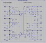
I have now try other gate driver models, it looks like the IR2113 Behavioral Model by analog is the cause of the trouble
or even a bug.
I did try in old 32 but LTspice, hmm sims faster more stable and cleaner but same trouble..
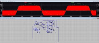
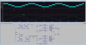
pic 1626 let also seen a big delay between the halves while it is exact the same circuit for BTL. that give a uge crossover
distortion.
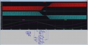
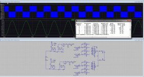
Pic 1629 is a sim with normal models for Gan, it is slow, but it do behave as expected, with common mode
voltage as is normal with multilevel systems. But it is now with a common mode filter out of fase as needed.
I do not now what is wrong with the IR2131 subcircuit, but there it go wrong.
regards
or even a bug.
I did try in old 32 but LTspice, hmm sims faster more stable and cleaner but same trouble..
pic 1626 let also seen a big delay between the halves while it is exact the same circuit for BTL. that give a uge crossover
distortion.
Pic 1629 is a sim with normal models for Gan, it is slow, but it do behave as expected, with common mode
voltage as is normal with multilevel systems. But it is now with a common mode filter out of fase as needed.
I do not now what is wrong with the IR2131 subcircuit, but there it go wrong.
regards
Attachments
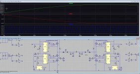
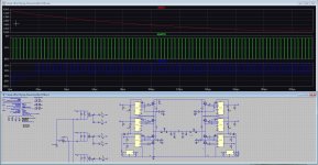
Jan. I have redrawn with LTspice own models, then things are oke. because these models are lossless there is no delay.Well if LTspice sees the same names in different places it concludes you want those nodes connected. It's not an LTspice bug.
That said, I do not know if LTspice considers labels in sub circuits as local. If so, that should work.
Jan
Th feedback circuit do work. Go try now other ways to use the models of interests.
This 5 level does have carrier 2 Mhz. 4 fold of original carrier.
Attachments
Wel last attempt is done, sub circuits do not work when use multiply versions in one schematic., special in opposite phase use like
BTL multilevel.
In some way it does see each other, and maybe the need to edit sub circuit names for each part make them uniek.
Normal models do work fine but are slow, and the ltspice behavior models do wel as expected.
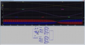
Did all kinds of tryouts, nothing works, the switching pulses are also very small, but when use one btl channel things get oke.
output is not in fase, even when I put in phaseshift 180 degree it does not work, I expect a lot of common mode voltage in the
model of the subcircuit because of wrong behavior and fase shifts.
I think even of a bug, because it has to be possible to use multiply subcircuits without this trouble because uniek names stuff.
Pic with yellow model do fine, but very slow, that is why I did use subcircuits. both circuits are same connected, no mistakes.
So conclusion, I need other models, and maybe writer of LT spice can look into this.
regards.
BTL multilevel.
In some way it does see each other, and maybe the need to edit sub circuit names for each part make them uniek.
Normal models do work fine but are slow, and the ltspice behavior models do wel as expected.
Did all kinds of tryouts, nothing works, the switching pulses are also very small, but when use one btl channel things get oke.
output is not in fase, even when I put in phaseshift 180 degree it does not work, I expect a lot of common mode voltage in the
model of the subcircuit because of wrong behavior and fase shifts.
I think even of a bug, because it has to be possible to use multiply subcircuits without this trouble because uniek names stuff.
Pic with yellow model do fine, but very slow, that is why I did use subcircuits. both circuits are same connected, no mistakes.
So conclusion, I need other models, and maybe writer of LT spice can look into this.
regards.
Attachments
ctrl-m did the job !I notice that ctrl-m works but ctrl-M does not??? And ctrl-j may work on linux/mac if ctrl-m does not.
Thanks steveu.
Anyone seeing this in the standard LT library for NPN devices. It's still showing this for me even after the latest update,


I have Ltspice for Mac, looks like that is different with Windows
i would like to change .op Data labels ( i have to many numbers after the dot).
I am not able to find how to do it with Mac..Please help Thanks
i would like to change .op Data labels ( i have to many numbers after the dot).
I am not able to find how to do it with Mac..Please help Thanks
Ya, standard.bjt: ".model 2SCR542F3 .... Vceo=1.00E+21 Icrating=1.00E+21" should be maybe "Vceo=30 Icrating=3".
https://fscdn.rohm.com/en/products/databook/datasheet/discrete/transistor/bipolar/2scr542f3tr-e.pdf
https://fscdn.rohm.com/en/products/databook/datasheet/discrete/transistor/bipolar/2scr542f3tr-e.pdf
Last edited:
Hello,
I'm trying to measure the slew rate of my circuit. How do I translate the slope in a readable V/us format.
Thanks a lot!

I'm trying to measure the slew rate of my circuit. How do I translate the slope in a readable V/us format.
Thanks a lot!
I'm not at my computer for a while but if you click and drag a box over the relevant portion of the waveform doesn't it give you a volts per second measurement in the lower left corner?
BTW it's hard to read your schematic but the green waveform doesn't look like slewing to me, it looks more like a bandwidth limit.
BTW it's hard to read your schematic but the green waveform doesn't look like slewing to me, it looks more like a bandwidth limit.
HiI'm not at my computer for a while but if you click and drag a box over the relevant portion of the waveform doesn't it give you a volts per second measurement in the lower left corner?
BTW it's hard to read your schematic but the green waveform doesn't look like slewing to me, it looks more like a bandwidth limit.
I do not understand the reading that it gives on the bottom left corner it reads x=24.52us and y=-2.80v but reading varies depending on where the + (indicator) hovers in the window area (not the cursor placement).
In the resulting window (my image) Diff (Cursor2-Cursor1) Slope: -2.25794e+007
Now I've read to calculate slew rate run a square wave to reach a triangle like form output. I've also read a freq of 100khz will do as estimate, this was what I did. I've executed a run at 100khz, input amplitude calculated at near clipping (0.6v) and at measured output max estimated full power of 50w.
Am I doing it correctly?
Thanks!
Good point! missed this part. I'll do a sim rerun again.Try removing the filter when looking for the amplifier slew rate.
Thanks!
Simply by using dv(…)Hello,
I'm trying to measure the slew rate of my circuit. How do I translate the slope in a readable V/us format.
Thanks a lot!
View attachment 1066542
- Home
- Design & Build
- Software Tools
- Installing and using LTspice IV (now including LTXVII), From beginner to advanced