I had again, after some months again a hanging LTspice, when this happens, control alt del do not good, even then it is almost not to stop.
There are bugs into this program I guess. But most of the time it do oke.
There are bugs into this program I guess. But most of the time it do oke.
I have a weird problem. In a dual triode LTP circuit there are degeneration resistors in the cathodes. If the value of these resistors is 82R, the simulation hangs. Every other value is fine. For now I use 81R.
I have a weird problem. In a dual triode LTP circuit there are degeneration resistors in the cathodes. If the value of these resistors is 82R, the simulation hangs. Every other value is fine. For now I use 81R.
I've come across that kind of thing quite often tbh.. Very strange. The last was one the sim of the Blomley amp. The bias setting resistors did something weird to the bias current at a specific value. Change them by a fraction either way and its all good,
Same can happen with large caps to.
If you choose to edit standard.bjt (etc.), the editor NPP+ has some great features. https://notepad-plus-plus.org/ Yes, I am an old "vi" and "awk" user, but time marches on.
1. First, you should keep each model to one line with no "+ ..." extension lines. This is important to facilitate other operations. You can join these lines by deleting all the "\r\n+" occurrences, ie the new lines followed by "+" at the beginning of the next line. The \r\n sequence may be different on a MAC etc. Do a search to see what you have.
2. You may also want to replace two spaces with one space until there are no double spaces, and " = " with "=", etc.
3. You can remove models that are not useful to you. For example, I have no use for Russian parts so I replace ^.USSR.$ with nothing. (using regular expressions) ie replace beginning of line, anything, target, anything, end of line, with nothing.
4. Under "Edit> line operations" you can remove all blank lines (containing spaces).
5. Under "Edit> line operations" you can sort lines ignoring case ( for .MODEL vs .model)
6. Under "Edit> line operations" you can delete duplicate lines.
7. but multiple occurrences of a model that are not identical is a bit more difficult. It's best if you do this manually but I ran out of patients and resorted to a batch file. Maybe someday I will write a script that makes a better choice, but for now, I just sort the models in npp+ and then using the batch file, delete all but the first copy of each model. At one time I was an "awk" guru but that was a long time ago in a Unix world. So I have hacked a batch file for the purpose. Batch files have terrible handling of variables and that complicates it a bit. You just drag and drop your sorted library (standard.bjt etc) file onto the batch file icon and the result is a new file called ~standard.bjt.nodup. This can take 10 seconds to do a large library file. If you have to repeat, be sure to delete the old output. The script simply does not copy lines with repeated models so they have to be sorted first. Note you can still get "duplicate models" from .lib/.incl statements on the schematic.
Nodup.bat:
@echo off
set model=
set fil=%1
FOR /F "tokens=1,2* delims= " %%i in (%1) do (
set lin=%%i %%j %%k
call :sub %%j
set model=%%j
)
pause
goto :eof
pause
:sub
if NOT "%model%"=="%1" echo %lin% >> %fil%.nodup
#3. is missing some stars. DIYA is deleting the asterisks . it should be ^.<star><target>.<star>$
When i am trying to copy and paste a new vactube model using the ".op" statement to netlest (SPICE directive button checked),
I am ending up with a very long string.
How can I split that up into several lines?
Tried to use Ctrl+M recommended at the bottom of that window without success.
I am ending up with a very long string.
How can I split that up into several lines?
Tried to use Ctrl+M recommended at the bottom of that window without success.
I'd really like some help from you guys!
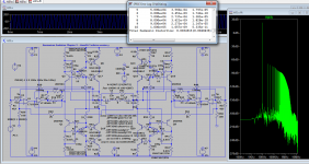
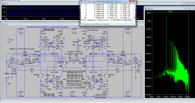
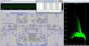
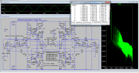
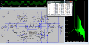
Maybe it's a simple problem for you but I don't get it.My simulator gives me very weird results from time to time, the computer has some problems and i can't even update it , but here's one dilema: what is the 22 ohms resistor doing or not doing in the first W1, 2,3, 4 pictures as the thd even at 100kHz shows better thd without it? Step response looks good anyway...in theory we all know those resistors are for making base charging and discharging faster, so what is the simulator not getting about it?
Second problem is what is the real dissipation of Q17?If I use any known power model except BD139C I get a lower dissipation, under 500mw, if I use BD139C i get half or more of the swing as the heat is shared almost eaqually between the two transistors in series.
If I remove q17 i get a fantastically low distortion amp running at 600mA idle current(even though the original Kenwood L01A from which I stole the output stage tells that idle current is actually 100mA ..
If I use q17 in the game, as in the first 4 simulations I have a class B amp with reasonably lor distortions and much lower idle current, around 5mA which was the entire point.I've run tons of simulations to get a clar idea of what i'd preffer doing because in class B q17 would be a germanium trasistor in my amp , but that trz can only take up to 2watts so ...should I risk trusting watt2 sim result or should I be cautious and dismiss the use of q17 all together base on watt1 sim results and on the fact that I acually get much muh lower distortions especially on lower impedances with the conveyor simple 1 transistor output ? That topology was simply copied after Kenwood L01A as I have the right transistors for that, but I wanted to have my germanium transistors embeded inside the loop even sacrificing some distortions figures for the class B trials.I'll probably check that circuit anyway, but I would have liked your opinion cause i'm really nervous at the idea of burning some germaium transistors that are really hard to find .
Attachments

Having a second though bd 139c simulation might actually be correct if the collector's potential of the conveyor made by q6 and q17 is the ratio of the gains of the transistors Aq11x Aq6 / Aq17 and that part of theory was missed by me. That makes the germanium trz use very unlikely ...
The 22 Ohm resistors do a couple things. First, a BJT power transistor (and others) requires a pull-off base current to turn it off quickly. This is why Darlingtons have resistors built in. Classic BJT amplifiers used 100 Ohms but that is a bit slow for 20KHz leaving amps to blow up from current shoot-through, depending on the particular transistor. Second, it is required to balance the drive to the NPN and PNP power transistors. Note the 33 Ohm for the other side.I'd really like some help from you guys!
Maybe it's a simple problem for you but I don't get it.My simulator gives me very weird results from time to time, the computer has some problems and i can't even update it , but here's one dilema: what is the 22 ohms resistor doing or not doing in the first W1, 2,3, 4 pictures as the thd even at 100kHz shows better thd without it? Step response looks good anyway...in theory we all know those resistors are for making base charging and discharging faster, so what is the simulator not getting about it?
Second problem is what is the real dissipation of Q17?If I use any known power model except BD139C I get a lower dissipation, under 500mw, if I use BD139C i get half or more of the swing as the heat is shared almost eaqually between the two transistors in series.
If I remove q17 i get a fantastically low distortion amp running at 600mA idle current(even though the original Kenwood L01A from which I stole the output stage tells that idle current is actually 100mA ..
If I use q17 in the game, as in the first 4 simulations I have a class B amp with reasonably lor distortions and much lower idle current, around 5mA which was the entire point.I've run tons of simulations to get a clar idea of what i'd preffer doing because in class B q17 would be a germanium trasistor in my amp , but that trz can only take up to 2watts so ...should I risk trusting watt2 sim result or should I be cautious and dismiss the use of q17 all together base on watt1 sim results and on the fact that I acually get much muh lower distortions especially on lower impedances with the conveyor simple 1 transistor output ? That topology was simply copied after Kenwood L01A as I have the right transistors for that, but I wanted to have my germanium transistors embeded inside the loop even sacrificing some distortions figures for the class B trials.I'll probably check that circuit anyway, but I would have liked your opinion cause i'm really nervous at the idea of burning some germaium transistors that are really hard to find .
However, I have doubts about the circuit. There is no natural mechanism to balance the voltage drop across the two power transistors. Bryston did something similar, but the NPN and PNP transistors were in parallel, not in series.
And you should put some space in your schematics. There is no need to cram everything together like that.
I mentioned already the base disharge role of the 22 ohms , what I don't get is why the simulator doesn't "see" the effect in theTHD at 100khz...Sims are weird...if you replace one or two 22ohms resistors in any part of the amp you'll see the thd drop several times which is pretty illogical until you chech the idle currents and you see they are not perfectly identical probably due to the op-amp offset.Perfectly simmetrical schematics aren't really simmetrical.
As for the other problem, after trying some more resistor values with bd139 in order to get different gains in the conveyor I completely abandoned the idea because the only reason to add that transistor was to make it class b with a germanium transistor as q17 .In the end I will go with the original kenwood l01a final stage modified sziklay pair as it shows the best distortion figures on lower impedances due to higher headroom and idle current and germanium trz for the first 4 input trz as I already explored that path and it works great .The original emitter resistor of q6 was 0.47 ohms and I'll be using 0.44(2x0.22).
I had another class b variation with just an emitter follower as the power output and that shows also very low thd but this kl01a version just looks sexy and I can revert to the 2ef stage anytime I want anyway.
Last edited:
I notice that ctrl-m works but ctrl-M does not??? And ctrl-j may work on linux/mac if ctrl-m does not.When i am trying to copy and paste a new vactube model using the ".op" statement to netlest (SPICE directive button checked),
I am ending up with a very long string.
How can I split that up into several lines?
Tried to use Ctrl+M recommended at the bottom of that window without success.
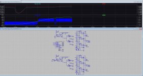
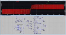
Without the 22 Ohm resistors, the outer power transistors just saturate and stay on continuously, leaving all the work to the inner transistors.I mentioned already the base disharge role of the 22 ohms , what I don't get is why the simulator doesn't "see" the effect in theTHD at 100khz...Sims are weird...if you replace one or two 22ohms resistors in any part of the amp you'll see the thd drop several times whichis pretty illogical until you chech the idle currrnts and you see they are not perfectly identical probably due to the op-amp offset.Perfectly simmetrical schematics aren't really simmetrical.
As for the other problem, after trying some more resistor values with bd139 in order to get different gains in the conveyor I completely absndoned the idea because the only reason to ad that transistor was to make it class b with a germanium transistor as q17 .In the end I will go with the original kenwood l01a final stage modified sziklay pair as it shows the best distortion figures on lower impedances due to higher headroom and germanium trz for the first 4 input trz as I already explored that path and it works great .The original emitter resistor of q6 was 0.47 ohms and I'll be using 0.44(2x0.22).
Could you please run my asc file with without the 22 ohms resistors and see if your simulator gives different results?
As expected, if you remove the 22 Ohm resistors, the collector voltages move to the rails.Could you please run my asc file with without the 22 ohms resistors and see if your simulator gives different results?
A rational for this topology occurs to me. The hotter or germanium transistor will begin to conduct (excessively) leaving the voltage load on the other transistor. So if you put a germanium transistor in series with a silicon transistor, as soon as it warms up, the germanium transistors begin to ~short leaving the silicon transistors to limit the current.
This reminds me of a "12 transistor radio" that a friend had when I was young. At the time, everyone had "6-transistor" AM radios, so I was keen to see what a 12 transistor circuit looked like. Well, turned out it was a 6 transistor circuit with 6 extra transistors wired as stubs, doing nothing. If you put germanium transistors in this circuit, what you have is an amp that can claim to use germanium transistors for marketing purposes, but where the germanium transistors are of little or no use. It becomes a clever engineering fraud that is only visible under sophisticated analysis.
The current conveyor theory doesn't help me with using a germanium trz in series and move it to class b that way, but the first 4 trz as gemanium trz are already tested in a headphones amp: https://www.diyaudio.com/community/threads/germanium-foundation-chapter1.381869/#post-6969861
The last post also have some simulations of a class b version with just 2ef .
The last post also have some simulations of a class b version with just 2ef .
Slightly OT: LTspice Tip of the Month:
https://www.analog.com/en/technical...W_P515800_MIX-NL-PN_1063&deliveryName=DM23004
Jan
https://www.analog.com/en/technical...W_P515800_MIX-NL-PN_1063&deliveryName=DM23004
Jan

Hi All
Everybody problems met copy and paste in the schematic?
I did double the circuit for btl service, I do not get it to work, one side only do work, copy do not.
If it work, I do not get fase shift in output when change inputs, it stays in fase. It is multilevel pwm,
I have common mode voltage, maybe this is a problem. So I did put in common mode filter.
Can be I did something wrong, I did made the connections right, not double names, no faults here.
As on the pictures the single original from the same schematic do work, pasted copy do not.
Thanks in advance
Attachments
Last edited:
Kees, one thing to be aware of is that you copy a circuit, the copy node names are the same as the original.
So if in the original you have the node 'output' it will be connected to the same node in the copy.
You really need to make sure (and if necessary modify names) so all node names are unique.
Jan
So if in the original you have the node 'output' it will be connected to the same node in the copy.
You really need to make sure (and if necessary modify names) so all node names are unique.
Jan
Hi Jan.Kees, one thing to be aware of is that you copy a circuit, the copy node names are the same as the original.
So if in the original you have the node 'output' it will be connected to the same node in the copy.
You really need to make sure (and if necessary modify names) so all node names are unique.
Jan
I have all names unique but it is not the first time I did forget a tiny name somewhere.
Like feedback names I have renamed, like feedbck is in copy feedbck1.
Maybe I need perse to use a differential opamp with one feedback circuit in a BTL amp, special
for fase shifts caused by components who are not precise the same value as always is.
- Home
- Design & Build
- Software Tools
- Installing and using LTspice IV (now including LTXVII), From beginner to advanced