That's too bad... There were 34 when I first saw them, and I bought 8. I'm definitely using 4 immediately, but if I don't need the others for the present then I'll let you know.Gone in 60 seconds. 🙁
I've been following the REW thread; it's very interesting. Are you using the internal oscillator in the Focusrite? Or something external like the Akitita mentioned in that thread?
I don’t need OP551. Disappointment was for others that would need them.
I’m using Focusrite internal oscillator. Its own distortion quickly rises with output level. IME, it is best to keep master “Monitor” output volume control below 1 o’clock position and adjust generator output in -3 to -10 dBFS level range, if possible in regard to required output level.
Focusrite loopback distortion minimal level is usually at 0.0003%. At limited low voltages, it can go down to 0.0001. Using “coherent averaging” option on distortion settings (available at latest REW versions), is very useful for low distortion measurement.
Oh yes, serving my M2 clone very well also
I’m very happy that it serves well someone else except me. Whole Pass Labs forum section is an example that one needs to share his designs.
I’m listening to the music this very moment and I simply can’t switch it off. LuDEF and some other good components are to be blamed. Pa and ZM as well.


Hi All,
I've been using the preamp shown in post #153 for some time now, and like it very much. I'm using it with diy F5 monoblocks, and Joseph Audio floorstanders, and it sounds great.
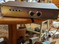
I haven't been able to do much diy recently, but over the last week or two I've finally started getting it into a more permanent chassis and I thought I'd share progress. Part of my goal here was to use up some of the surplus items I've collected over the last few years, partly due to my ebay habit. I decided on a dual mono build, partly because I had a pair of nice Holden & Fisher toroids I wanted to use (at 50VA these are way bigger than necessary). I'm using a steel case I got from Surplus Sales in Nebraska that previously had a prehistoric NABU pre-internet computer thing in it, a pair of big old 20-turn precision pots from some old equipment or other (one per channel - I like doing it this way for some reason), and a pair of Cole rotary switches (not visible in photos).
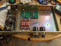
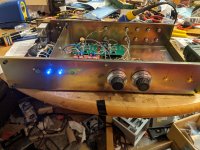
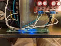
Present state of affairs is as shown, following putting the power indicator LEDs in this evening. Power switch and fuse in back panel at left, trafos are screened off by the convenient steel divider in the case, followed by dual 7815/7915 regulator circuits (one for each channel) and then the boards themselves are the same as reported earlier in the thread. Signal wiring will all be cleaned up in a final version. The little pcb supporting the indicator lights is repurposed from the chassis's earlier incarnation. For the present there's just one input so I can use it while I plan out the things that remain to be done. The front (and back?) of the chassis is going to be sanded/polished and then "blued". Should give a nice glossy near-black finish, with a little luck. I'll fit a small plate (maybe stainless?) over the four holes, so only the two I need are visible. Switches for the inputs are going to be on steel rods to make the signal wiring as short as possible; you can see the bushings on the front plate to the right of the volume pots. One switch per channel; if switching them separately gets annoying I might try some sort of mechanical linkage, like EUVL used somewhere else on the site. I had also planned to put the volume pots on rods also to get them as close as possible to the boards, but the way they connect to their dials makes it awkward; so for the time being I've put them in as seen.
One possibility I've been wondering about is to use relays to switch the inputs. I know relays can be helpful in keeping signal wiring short, but in this case it'll be short anyway. Are there other arguments for using them that I'm missing?
tombo56: Thanks again for your work on this and making it all available.
Best
Nigel
I've been using the preamp shown in post #153 for some time now, and like it very much. I'm using it with diy F5 monoblocks, and Joseph Audio floorstanders, and it sounds great.
I haven't been able to do much diy recently, but over the last week or two I've finally started getting it into a more permanent chassis and I thought I'd share progress. Part of my goal here was to use up some of the surplus items I've collected over the last few years, partly due to my ebay habit. I decided on a dual mono build, partly because I had a pair of nice Holden & Fisher toroids I wanted to use (at 50VA these are way bigger than necessary). I'm using a steel case I got from Surplus Sales in Nebraska that previously had a prehistoric NABU pre-internet computer thing in it, a pair of big old 20-turn precision pots from some old equipment or other (one per channel - I like doing it this way for some reason), and a pair of Cole rotary switches (not visible in photos).
Present state of affairs is as shown, following putting the power indicator LEDs in this evening. Power switch and fuse in back panel at left, trafos are screened off by the convenient steel divider in the case, followed by dual 7815/7915 regulator circuits (one for each channel) and then the boards themselves are the same as reported earlier in the thread. Signal wiring will all be cleaned up in a final version. The little pcb supporting the indicator lights is repurposed from the chassis's earlier incarnation. For the present there's just one input so I can use it while I plan out the things that remain to be done. The front (and back?) of the chassis is going to be sanded/polished and then "blued". Should give a nice glossy near-black finish, with a little luck. I'll fit a small plate (maybe stainless?) over the four holes, so only the two I need are visible. Switches for the inputs are going to be on steel rods to make the signal wiring as short as possible; you can see the bushings on the front plate to the right of the volume pots. One switch per channel; if switching them separately gets annoying I might try some sort of mechanical linkage, like EUVL used somewhere else on the site. I had also planned to put the volume pots on rods also to get them as close as possible to the boards, but the way they connect to their dials makes it awkward; so for the time being I've put them in as seen.
One possibility I've been wondering about is to use relays to switch the inputs. I know relays can be helpful in keeping signal wiring short, but in this case it'll be short anyway. Are there other arguments for using them that I'm missing?
tombo56: Thanks again for your work on this and making it all available.
Best
Nigel
Attachments
If mechanical switches will be close to the rear panel, I don’t see any important advantage of relay switches, as wires will be short. Something like Salas’ I-select would allow more tidy build.
With all those long unshielded wires, seems that steel case is your savior against hum. 🙂
With all those long unshielded wires, seems that steel case is your savior against hum. 🙂
If mechanical switches will be close to the rear panel, I don’t see any important advantage of relay switches, as wires will be short. Something like Salas’ I-select would allow more tidy build.
I'll look into the I-select, but lacking any good reason to use relays I think I'll stay with the plan to mount the switches close to the back.
With all those long unshielded wires, seems that steel case is your savior against hum. 🙂
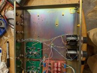
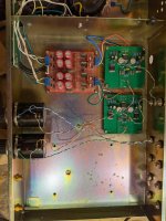
No hum problem as things are; at full volume with my ear against the speaker grille I can hear hum, but nothing is audible at normal volumes and/or distances. Nonetheless you may be right about the steel case being my saviour, of course, and in any event the long wires are bad practice, and should be shortened in the final version, just on general principles if nothing else. I tidied the ground wires up today (and increased the resistors on the LEDs, which were too bright). Photo attached. To shorten the input signal wires I will need to put the volume pots at the back; there's plenty of vertical room to mount one of the buffers above the other to make space for the pots, if I can figure out how to keep the dials on the front. Shouldn't be too hard.
Alternatively, I'm tempted to try an AVC. Maybe the slagle audio $300 ones that used to be the $200 ones. There's enough space in the chassis, although it's not clear whether there is enough space in my budget.
Attachments
I have no experience with AVC volume controls, but any stepped regulator is a wrong solution for me, as optimal volume level is always in between two steps. 🙂
I can recommend Muses volume control solutions like Meldano’s Muses V2:
https://www.diyaudio.com/community/threads/muses-volume.322983/
One build blog: https://www.diyaudio.com/community/...c-volume-control-build-from-wisconsin.370993/
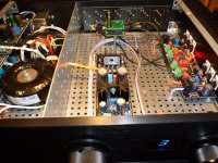
It is wonderfully transparent volume control with precise attenuation and adjustable balance. IMO, it is far better than any ordinary potentiometer. Remote control is additional benefit. It can be used as simple volume control module or as a complete input switching and volume control solution.
At attached picture, small green PCB is Meldano’s Muses V2 volume control in my preamplifier.
I can recommend Muses volume control solutions like Meldano’s Muses V2:
https://www.diyaudio.com/community/threads/muses-volume.322983/
One build blog: https://www.diyaudio.com/community/...c-volume-control-build-from-wisconsin.370993/
It is wonderfully transparent volume control with precise attenuation and adjustable balance. IMO, it is far better than any ordinary potentiometer. Remote control is additional benefit. It can be used as simple volume control module or as a complete input switching and volume control solution.
At attached picture, small green PCB is Meldano’s Muses V2 volume control in my preamplifier.
Attachments
there is high possibility that, once you hear difference between resistive and proper inductive attenuation, you'll change your mind
though, as we have a sayin' - 100 ljudi 300 sisa ....... everyone is entitled to own taste
though, as we have a sayin' - 100 ljudi 300 sisa ....... everyone is entitled to own taste
My opinion as why a proper AVC (read that as Iron Turtle 😀) sounds dynamic, even at low levels, is that there is no magic in signal energy preservation but rather brutally low AVC output impedance, that makes a difference while driving the following stages.
As well, I agree that there is no existential difference between opinion and a*se, everybody has one. 🤣
As well, I agree that there is no existential difference between opinion and a*se, everybody has one. 🤣
I've become used to using separate L and R volume controls, partly because sometimes I want to adjust balance, and this is a simple way to do it. Using multiturn pots also gives quite fine control when I want it. Tombo56's argument about stepped attenuators applies here; if the steps are too large then the control isn't very fine. (Although there has to be sufficiently large number where it would be fine enough, I suppose.) This is one argument against AVC, IMHO. Another argument against is the cost, of course; I haven't heard an AVC control, and it's a lot to spend if I'm not happy with the outcome.
On the other hand, I like old-school approaches to things, in general. I almost always prefer hand tools over electric ones when woodworking (which is actually my main hobby). I like BW photography on film, home development, optical printing, and purely mechanical cameras. Not because any of these are really better than modern alternatives; just that doing things this way appeals to me. And I like the idea of using iron and copper rather than silicon (which I think I've heard ZM say elsewhere?), so an AVC appeals to me for these non-audio reasons. (It's a miracle I haven't migrated to building with tubes, now I think about it. 🙂)
It seems that intact audio offer a 28-step pair that I could use as twin mono controls. ZM: is there an Iron Turtle option that might suit? Looking through the site I can see stereo SE and balanced but I'm not sure if a pair of mono is an option? Any other suggestions?
I'll look into the muses business to see whether something there appeals.
My opinion as why a proper AVC (read that as Iron Turtle 😀) sounds dynamic, even at low levels, is that there is no magic in signal energy preservation but rather brutally low AVC output impedance, that makes a difference while driving the following stages.
As well, I agree that there is no existential difference between opinion and a*se, everybody has one. 🤣
nope, verified in tests ....... using buffer OS (Papa's Koan) so entire attenuation range covered in listening
said in exact terms ......... testing setup which cemented my insane wish of making my own AVC
Case 1. 10K TKD (skup ko zmija) followed with buffer having Rout in range of few ohms; buffer fed with decent shunt regs; beside that type, I did tried all possible less and more expensive resistive attenuator solutions; name it ..... covered
Case 2. Slagle 200$ AVC package*** ( now 300$), having simple complementary JFet buffer in front *fed with decent shunt reg)
I did go that far to set Rin of buffers (Case 2) to 10K, so same Rin as Case 2
extensive enjoyment tests conducted, same as punctual ones ( precisely set output level) ...............
Case 1 set to -6db
Case 2 set to -6db
result being pretty much same Rout
there is something in Signal Energy Preservation BS, at least to my ears ( and eyes!!)

again, why should I act different than other people and why shouldn't I push water to my own mill ......
but I'm even not selling my Drek per se - zillion times I wrote - whoever is interested, just try *** with your B1, and let your ears decideanyway, in short , nope - Rout not involved in entire story
Last edited:
I've become used to using separate L and R volume controls, partly because sometimes I want to adjust balance, and this is a simple way to do it. Using multiturn pots also gives quite fine control when I want it. Tombo56's argument about stepped attenuators applies here; if the steps are too large then the control isn't very fine. (Although there has to be sufficiently large number where it would be fine enough, I suppose.) This is one argument against AVC, IMHO. Another argument against is the cost, of course; I haven't heard an AVC control, and it's a lot to spend if I'm not happy with the outcome.
On the other hand, I like old-school approaches to things, in general. I almost always prefer hand tools over electric ones when woodworking (which is actually my main hobby). I like BW photography on film, home development, optical printing, and purely mechanical cameras. Not because any of these are really better than modern alternatives; just that doing things this way appeals to me. And I like the idea of using iron and copper rather than silicon (which I think I've heard ZM say elsewhere?), so an AVC appeals to me for these non-audio reasons. (It's a miracle I haven't migrated to building with tubes, now I think about it. 🙂)
It seems that intact audio offer a 28-step pair that I could use as twin mono controls. ZM: is there an Iron Turtle option that might suit? Looking through the site I can see stereo SE and balanced but I'm not sure if a pair of mono is an option? Any other suggestions?
I'll look into the muses business to see whether something there appeals.
I did wrote several times - cheapest Slagle solution is having straight series taps arrangement, straight through simple in that that you want to set it to have some gain on poutput
whichever of his , you can use, but taking care of switching arrangement ( some having 2 combining switches per channel) and these are actually complicated for "with gain" iteration
my life is already too complicated, so decided to not sell any part of IPumpkin package separately, so no Motherboard as item and no Turtle as item
btw. ITurtle (both SE and non-SE) are dual mono, signal side; SE can't have relays operated to have balance ; Bal can - having separate pcb and relays set per channel, just matter of separate 24step switches (one per channel)
sorry Tombo, no more Iron talk here ............
Going OT was my fault, I think... sorry. In any event, thanks to both of you.sorry Tombo, no more Iron talk here ............
If you both find it convenient, just carry on.
It’s all connected and on topic. Volume controls, buffers, preamplifiers ..
It’s all connected and on topic. Volume controls, buffers, preamplifiers ..
Hi Tombo,
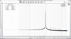
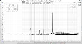
So you may have had a good point about the long signal wiring, even if fhere is no audible hum. I spent a while fiddling about with REW again; the two plots below show first the loopback for the Focusrite Solo, and then the result when using the buffer. The settings on the Focusrite were the same in both cases, and the volume on the buffer preamp set to give the same output voltage (as measured by DMV) as the oscillator in the Focusrite. The numbers for each harmonic are very close to each other, so the buffer is adding little or no
distortion, but the noise is worse, all apparently multiples of 60Hz. This looks worse than the plots in post #153 whcih were the exact same buffer boards in a temporary case with external PSU (although the test setup may not have been exactly the same) so it seems likely the cause of the forest is having the PSU in the case, and the signal wiring picking the mains noise up.
None of this is audible, of course, being about 90dB down or more, but it's there so I want to see what can be done. I have some twisted and shielded/screened signal wiring I can try, so I'll try wiring up the inputs and volume pots with more care and see what happens.
Anything else simple I can try? Short of rebuilding with external PSU, that is? (I'm not fiddling around with switching inputs for the time being, just hardwiring one.)
Attachments
If your arrangement is still the same as in the pictures in post #166, there are a couple of easy things to try. First, twist all your power wires (+,-, GND) tightly to reduce loop areas. Another thing would be to move the buffer boards further away from your power supply; you have lots of room.
You could do it in stages and remeasure with REW to see how the changes affect the noise.
You could do it in stages and remeasure with REW to see how the changes affect the noise.
Thanks for the input. Twisting the power wires is an easy thing to try, I'll certainly give it a go. And yes, I can move the buffer boards; in fact there's enough space to mount them vertically, so there are plenty of possibilities for where to put them without getting in the way of the input switches and extenders that will be going in the big space on the right.
I'm a little surprised that the steel dividor in the case isn't enough to shield everything from the transformers.
I'm a little surprised that the steel dividor in the case isn't enough to shield everything from the transformers.
I had noise issues as well when I built my LuminAria preamp. I installed a steel divider, also. It helped but did not block all the noise from the power supply.
None of this is audible, of course, being about 90dB down or more, but it's there so I want to see what can be done. I have some twisted and shielded/screened signal wiring I can try, so I'll try wiring up the inputs and volume pots with more care and see what happens.
There will be no need to rework preamplifier and move power supply. All 60 Hz noise is EMI that unshielded wires pick up. As buffer has onboard super regulators and there are LM pre-regulators as well, nothing measurable will come through supply. As a reference, look at buffer output noise level with shorted input. That is calibrated measurement and 50 Hz noise is at 100 nV level or 140 dB below 1 V. Even that 100 nV doesn't come from the buffer output but is what well shielded measurement cable always picks up as a minimum environment noise.
Just use shielded cable for all signal paths and it will be fine. 🙂
Also, use only proper shielded interconnect cable between preamplifier and ADC input. That is also a point of noise pickup.
Why do you have REW reference level set as 124000 V (124 kV)? There is usually used 1V or max. interface input level. In case of Focusrite max. input is 7.75 V or + 20 dBU.
There will be no need to rework preamplifier and move power supply.
Good. Because that's not in the cards anyhow...
All 60 Hz noise is EMI that unshielded wires pick up. As buffer has onboard super regulators and there are LM pre-regulators as well, nothing measurable will come through supply.
This makes perfect sense to me, if by "coming through supply" you mean electrically, through V+, V- and GND to the buffers. On the other hand the plots in post #153 don't show this EMi interference, and the only difference was the external PSU (same buffer boards, also long twisted-pair signal wiring, same position in house when measured, same Focusrite). So it looks like the problem should be connected with the internal PSU somehow. Is it possible the transformers or the 7815/7915 board are the source of the EMI? Of course it may be operator error with REW or the Focusrite - I'm hardly an expert 🙂
Just use shielded cable for all signal paths and it will be fine. 🙂
Just to be clear, by "shielded" do you mean single-core coax, with the core carrying the signal and the shield carrying the ground? Or something more sophisticated? I have some small two-core shielded cable here (although I can't remember why I bought it) so I could use that with the signal and ground carried by the core, and ground the shield at one end (presumably). Any better than one-core? At least, not any worse? Looking around other threads on the site advice on this point seems to vary a lot; some people (I think Mark Johnson said this somewhere) prefer carrying ground in the shield, and grounding the second core wire at one end only. Thoughts? (I don't have any quality single-core coax here, except heavier stuff I use for interconnects, which doesn't seem ideal.
Also, use only proper shielded interconnect cable between preamplifier and ADC input. That is also a point of noise pickup.
I'm using single-core coax connected to an XLR, and the microphone input on the Focusrite. I'm using a 47k load acrss the preamp output. (Although I wonder whether there's any point in this. The Focusrite itself should be OK as a load, right?) If any of this doesn't sound right please let me know. In any event I used exactly the same cables to produce the loopback measurement, and that didn't show the EMI interference, so it seems unlikely to me that it's the cause.
Why do you have REW reference level set as 124000 V (124 kV)? There is usually used 1V or max. interface input level. In case of Focusrite max. input is 7.75 V or + 20 dBU.
I have no idea why it's set to that. 😳 It was probably set to that by default when I installed REW, and I never changed it. You see, I told you I wasn't an expert... although that was probably already pretty obvious.
Some fun stuff to try today! Thanks for the input.
- Home
- Amplifiers
- Pass Labs
- Input buffer for LuDEF, SissySIT and similar amplifiers