No need for more creative naming. That is required if you can’t design something new, so you attach fancy name to something ordinary.Perhaps more like "Heresy"?
ZM’s designs are a rare example where along with new and original design goes also very unique project name. Pa should borrow from him. That F1,F2,F3,F4… naming scheme is boring, though being always something new and original, fancy names are not required. 😀
Hi @tombo56,
This buffer has been the front end to my M2 Clone amp for some time and now its time for a change. My plan is to replace the M2 Clone boards with EUVL's M2OPS amp boards. Since no more Iron for gain, the buffer will be adjusted to provide 12dB.
My question is how/where to connect these two boards?
For M2OPS SE input, -In will is jumperd to GND.
I'm thinking buffer signal output should connect directly to the vacated M2OPS opamp (U4) pin6 location.
Next question, does C2 need to be in the signal path since TomboBuffer has ultra low DC offset at output?
Power for the buffer could use pins4/7 from U4 socket or come directly from power supply board, which would be preferred?
M2OPS schematic is attached.
Thanks!
Attachments
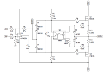
That would be the right connection point. C2 should remain as Q2 gate is not on the ground potential.I'm thinking buffer signal output should connect directly to the vacated M2OPS opamp (U4) pin6 location.
But, that buffer can’t provide more than 11 Vrms at the output (with readjustment of on-board regulators to +/- 18V supply. Is this enough for intended use? M2 output stage can provide more.
 nitpicking:
- buffer, colloquially taken as impedance "converter". without voltage gain
- issue with C2 - always think what's voltage on both sides of it; Tombo's buffer free of DC Offset, but other side of C2 isn't - just to make a lesson from Tombo's reply
Isn’t diy electronics great?
With one resistor change, buffer is transformed into VAS.
With some another part change, it can be transformed into magic smoke.
Never ending fun. 😀
With one resistor change, buffer is transformed into VAS.
With some another part change, it can be transformed into magic smoke.
Never ending fun. 😀
Ahhh, foiled again!
My enthusiasm got the better of me, and if I paid closer attention to Patricks write up, not wise to remove C2 as you fellas also mention.
Thanks!

FE2022 is probably a better option.
My enthusiasm got the better of me, and if I paid closer attention to Patricks write up, not wise to remove C2 as you fellas also mention.
Thanks!
FE2022 is probably a better option.
Yes, it is.FE2022 is probably a better option.
But OPA551 is also very good for audio. It has proper JFET inputs and distortion is very low.
That was the first opamp I used, then switched to OPA604.
I was looking to complicate things with this re-model 😂.
I wasn’t too far down the road and can change plans to use FE22 instead.
I was looking to complicate things with this re-model 😂.
I wasn’t too far down the road and can change plans to use FE22 instead.
It was not a question but answer. 🙂
It would perform depending how circuit is designed.
Requirements -> design solutions -> results -> evaluation
Someone has to perform all steps and answer. I can't.
It would perform depending how circuit is designed.
Requirements -> design solutions -> results -> evaluation
Someone has to perform all steps and answer. I can't.
yes I understand, my question was more generic has someone already tried a unity buffer with opa551? was he satisfied?
to avoid building one and then be disapointed
to avoid building one and then be disapointed
if you take OP as part, considering it's role - you'll always find several types presumably (and certainly) working equally good
so, no reason that any of them is suddenly hoppla! Mana from Heaven
same as proof is in da pudding, quality of stage is in execution - so , whatever (important!) PSU/reg, properly routed pcb and - not less important - impedances in NFB loop
so, yes - any decent OP will be happysounding buffer. when made properly
opa551 included
if it's decent - dunno, didn't check datasheet
- Home
- Amplifiers
- Pass Labs
- Input buffer for LuDEF, SissySIT and similar amplifiers