IME, integrated circuits are pretty tolerant on prolonged heating and multiple soldering/de soldering operations. I have one OPA828 that has gone through 5 heating cycles being soldered and removed from two PCBs, to work flawlessly on the third.
You can safely remove OPA from the PCB using hot plate at 250 – 300 deg. Heat the PCB and try to lift IC with tweezers or small pliers. It will just detach at proper temp.
PCB in question may not remain in perfect condition after thorough heating, but you probably have a spare one.
You can safely remove OPA from the PCB using hot plate at 250 – 300 deg. Heat the PCB and try to lift IC with tweezers or small pliers. It will just detach at proper temp.
PCB in question may not remain in perfect condition after thorough heating, but you probably have a spare one.
Thanks. Fingers crossed on the OPA551. Should be OK, I guess, they look pretty burly as far as heat is concerned.IME, integrated circuits are pretty tolerant on prolonged heating and multiple soldering/de soldering operations. I have one OPA828 that has gone through 5 heating cycles being soldered and removed from two PCBs, to work flawlessly on the third.
You can safely remove OPA from the PCB using hot plate at 250 – 300 deg. Heat the PCB and try to lift IC with tweezers or small pliers. It will just detach at proper temp.
PCB in question may not remain in perfect condition after thorough heating, but you probably have a spare one.
I'll try the hot plate. William2001's soldering tip looks cooler, but since I don't have one and do have a hot plate the way forward seems pretty clear. (I'm not concerned about the board. They were not expensive and I have spares.)
Best
Nigel
I had mine plating with an input voltage of about +-43 volt. The boards became pretty hot after a while. Is that expected or is something amiss...
At +-43V boards are expected to be pretty hot. Nothing to worry if temperature is even up to 60 deg. Celsius. At high supply voltages, it would be good to have boards in vertical position, as both front and back PCB surfaces are used as heatsinks.
What amplifier/input transformer are you driving with this buffer?
What amplifier/input transformer are you driving with this buffer?
If buffer can’t be mounted in vertical position, at both top corner surfaces can be added adhesive heatsinks up to 25x25 mm like:
adhesive heatsink
adhesive heatsink
great advice! I use them with the latest sony vfet project from Nelson, the P-version. Just on the workbench so no evaluation yet...
You probably have this +-43V supply from some previous project. It’s OK but anything from +- 18V and up is enough. Another option is to use existing 36V supply and to get another rail using affordable DC-DC converter like:
DC-DC converter
DC-DC converter

Here's a progress report and some pics...
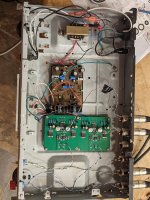
I have the buffers up and running in a temporary chassis, which was recently used for my first version of ZM's Iron Pre and was available to get power to the boards and signal in and out. (The wiring is temporary and chaotic...) I tried it first with an EI transformer and the p2p Good Gemini shunt PSU that I wrote about elsewhere; that setup is shown in the first photo. Seemed to work just fine, at least on REW, but the plot showed several bumps from mains 60Hz and harmonics. My guess is that the EI transformer was interfering with the chaotic wiring, so I tried again with an external supply - a 7815/7915 doodad I made years ago using a schematic from Rod Elliott's site; shown in the second photo, with much better results.
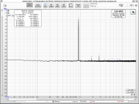
I used REW with a Focusrite Solo and laptop. The plots show, in order: a loopback, right channel at full output and then partial output (about where I usually seem to end up listening, about 0.2V). Left channel is very similar so I omitted it. Just 0.00045% THD! Considering the loopback already showed 0.00039% I'm sure that my measurement techniques (or perhaps the Focusrite) are the limiting factor here, not the buffers. Either way an expcetional outcome, I;d say...
I have it hooked up it my system and it sounds great! Now I have to decide how to arrange things more permanently. An AVC seems a good idea (maybe ZM's Iron Turtle?), but there are so many things to try... 🙂
Tombo: Thanks very much for your work on this, and for making it available to us; I think it's great.
Best
Nigel
I have the buffers up and running in a temporary chassis, which was recently used for my first version of ZM's Iron Pre and was available to get power to the boards and signal in and out. (The wiring is temporary and chaotic...) I tried it first with an EI transformer and the p2p Good Gemini shunt PSU that I wrote about elsewhere; that setup is shown in the first photo. Seemed to work just fine, at least on REW, but the plot showed several bumps from mains 60Hz and harmonics. My guess is that the EI transformer was interfering with the chaotic wiring, so I tried again with an external supply - a 7815/7915 doodad I made years ago using a schematic from Rod Elliott's site; shown in the second photo, with much better results.
I used REW with a Focusrite Solo and laptop. The plots show, in order: a loopback, right channel at full output and then partial output (about where I usually seem to end up listening, about 0.2V). Left channel is very similar so I omitted it. Just 0.00045% THD! Considering the loopback already showed 0.00039% I'm sure that my measurement techniques (or perhaps the Focusrite) are the limiting factor here, not the buffers. Either way an expcetional outcome, I;d say...
I have it hooked up it my system and it sounds great! Now I have to decide how to arrange things more permanently. An AVC seems a good idea (maybe ZM's Iron Turtle?), but there are so many things to try... 🙂
Tombo: Thanks very much for your work on this, and for making it available to us; I think it's great.
Best
Nigel
Attachments


Incidentally, I forgot to mention that I made the changes Tombo suggested above for (a) a +/- 15V supply (changed the four R to 4k7) and (b) a preamp (changed C5 to 33pF).
Another one plays fine music. 
EI transformers have strong stray fields and, in combination with long unshielded input wires, some 60 Hz noise would show on the measurements. 7815/7915 supply is a very good solution.
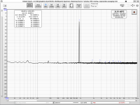
If shielded cable would be used at input, I think that EI transformer in the same case would be fine. Rest of cabling can remain as is. PCB itself is designed to provide high isolation from surrounding EMI. Here is one noise measurement made on the bench with dual big unshielded EI transformers (old lab PS) only 20 cm apart from the buffer:

This measurement was made with calibrated LNA (1000x Low Noise Amplifier). 50 Hz EMI noise is at 100 nV or -140 dBV level.
EI transformers have strong stray fields and, in combination with long unshielded input wires, some 60 Hz noise would show on the measurements. 7815/7915 supply is a very good solution.
If shielded cable would be used at input, I think that EI transformer in the same case would be fine. Rest of cabling can remain as is. PCB itself is designed to provide high isolation from surrounding EMI. Here is one noise measurement made on the bench with dual big unshielded EI transformers (old lab PS) only 20 cm apart from the buffer:
This measurement was made with calibrated LNA (1000x Low Noise Amplifier). 50 Hz EMI noise is at 100 nV or -140 dBV level.
Hi All,
If anyone is looking for OPA551, Digikey shows 26 OPA551FA/500G3 in stock:
https://www.digikey.com/en/products/detail/texas-instruments/OPA551FA-500G3/1572794
I just bought a few, since I'm planning on building more of these buffers; the pair I have running in the temporary arrangement sound great.
Tombo: I haven't tried the shielded input wires with the EI, since I'm looking into a more permanent chassis which may make the point moot. Your noise measurements are very impressive; can I ask what setup you used? It looks like you're using REW, but what interface? Your earlier THD and N measurements also show much lower noise than mine, which might be due to better equipment or (more likely) a better setup and more experience. Interested to hear more if you have the time.
Best
Nigel
Last edited:
My first pair of these 'buffer' are playing in pre-amp mode, r12 2k7 and a smaller c5, they are providing juice to the latest vfet version from Nelson. It sounds amazing. Thank you very much for this gem
I’m very happy that it serves well someone else except me. Whole Pass Labs forum section is an example that one needs to share his designs.
I’m listening to the music this very moment and I simply can’t switch it off. LuDEF and some other good components are to be blamed. Pa and ZM as well.
Your noise measurements are very impressive; can I ask what setup you used? It looks like you're using REW, but what interface?
As you say, some practice helps to get better results. I was making a lot of mistakes in the beginning. Noise measurements are possible only with additional Low Noise Amplifier. I’m using this one: Groner's LNA
along with Focusrite Scarlett Solo gen.3 and some good cabling.
Lot of information is available in the REW thread: Measurement with REW
When preparing for the next measurements, just ask to check setup with you.
Gone in 60 seconds. 🙁Hi All,
If anyone is looking for OPA551, Digikey shows 26 OPA551FA/500G3 in stock:
https://www.digikey.com/en/products/detail/texas-instruments/OPA551FA-500G3/1572794
- Home
- Amplifiers
- Pass Labs
- Input buffer for LuDEF, SissySIT and similar amplifiers