Very flat, the acoustic band, looks characterization 741. Dependence Vdif the delay is something else entirely.
No.
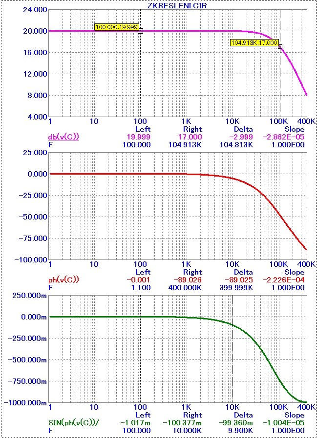
The basic problem of the uA741 is very low slew rate, 0.5V/us. Compared to this, the circuit I am showing has a slew rate of 250V/us. Thus, it can never dynamically saturate in audio use, especially if RC input filter tuned somewhere at 500kHz is used.
I have also shown the full-scale, 24Vp-p output at 1MHz. With uA741, it is only 8kHz!!
Attachments

Last edited:
It is not proofs, Federmann! Did you make some well organized blind test with many persons ? With which results ? Do you can to write this ?
... Very poor uA741 gives poor results, nothing new.
Do you think that another good OZ, will be at delayed 10° better results?
Do you think that another good OZ, will be at delayed 10° better results?
Again, you speak about phase shift (and you do not mention frequency and slew rate).
Answer my question - I have shown 24Vp-p 1MHz undistorted measured, not simulated, output. You speak about uA741 that distorts at 8kHz full scale sine due to slew rate of 0.5V/us. Why do you use such example??
I replied here: http://www.diyaudio.com/forums/soli...-listening-characteristics-3.html#post1989165
Last edited:
Try it, I did..Do you think that another good OZ, will be at delayed 10° better results?
We are not talking about opamps, but about your statement, so answer! Or you don't understand ?
First post
I would like to ask what, who sees the link between delays and ...
Thank
Listening correlation, Federmann, listening correlation... How many times I must ask you, then I get answer ? Or are you Green hubby from UFO ?
I view, that the maximum acceptable delay is 5.7 ° for the entire frequency band to 200kHz. Sinus 5.7 ° is exactly 1 / 10 output signal, but you certainly read on my web.
I'm interested in the views and experience of others.
I'm interested in the views and experience of others.
Again no answer...you have really good " input filter " for straightforward questions....
I can only repeat what I wrote.
I view, that the maximum acceptable delay is 5.7 ° for the entire frequency band to 200kHz. Sinus 5.7 ° is exactly 1 / 10 output signal, but you certainly read on my web.
I'm interested in the views and experience of others.
Why? Why not 5 or 6 degrees???Because you believe it?view, that the maximum acceptable delay is 5.7 °
Why? Why not 5 or 6 degrees???Because you believe it?
I also wrote: „is exactly 1 / 10 output signal, but you certainly read on my web.“
There can read that 1/10 signal, the power output is 1/100 of 1%. We can talk about the distortion of 1%.
Really ? And if not ? Transistor sound ? Your statement have certainly good background, obtained by many listening tests...can you describe them ? Our community goes on the wrong way fifty years and we watch new ideas...
I still see that there is no experience. Nobody associated delays and sound?
The topic is not about presenting their own equipment, the theme is about knowledge, as assessed by the amplifier delay.
The topic is not about presenting their own equipment, the theme is about knowledge, as assessed by the amplifier delay.
Only interchannel delay (phase shift) is audible.
This is not a topology, there is not a hearing delay. This is the delayed signal is compared with the input signal.
Delays 5.7°, the output signal passes through zero, but the input signal has a 10% maximum value.
Increase Vdif corresponds in the distortion. Shape Vdif corresponding to the deviation from the original signal.
Again, you speak about phase shift (and you do not mention frequency and slew rate).
Answer my question - I have shown 24Vp-p 1MHz undistorted measured, not simulated, output. You speak about uA741 that distorts at 8kHz full scale sine due to slew rate of 0.5V/us. Why do you use such example??
I replied here: http://www.diyaudio.com/forums/soli...-listening-characteristics-3.html#post1989165
If, you answered, delayed 10 °, it would Vdif = arcsinus 10 °
Vdif for 10 ° = 17.4%, as well as the 741.
Linear change (amplitude and phase) is normally not called distortion. As a 'distortion' we mean nonlinear distortion, i.e. creation of new frequency components not present in an original input signal. You speak about shape of amplitude and phase plot.
Your example with uA741 has nothing in common with phase shift. You are showing strong nonlinear distortion, resulting from slew rate limit. This nonlinear distortion creates new harmonics. Thus, your question on 5.7 degrees makes not much sense. You can ask for wide bandwidth, but you must same time ask for high slew rate.
Your example with uA741 has nothing in common with phase shift. You are showing strong nonlinear distortion, resulting from slew rate limit. This nonlinear distortion creates new harmonics. Thus, your question on 5.7 degrees makes not much sense. You can ask for wide bandwidth, but you must same time ask for high slew rate.
If, you answered, delayed 10 °, it would Vdif = arcsinus 10 °
Vdif for 10 ° = 17.4%, as well as the 741.
10 ° at 475kHz, in case of my preamp. uA741 would show nothing but sawtooth line of very small amplitude at 475kHz. Not because of phase shift, but because of limite slew rate (0.5 V/us). You shoul learn basics of operational amplifiers.
- Status
- Not open for further replies.
- Home
- Amplifiers
- Solid State
- Influence of the delay amplifiers for listening characteristics