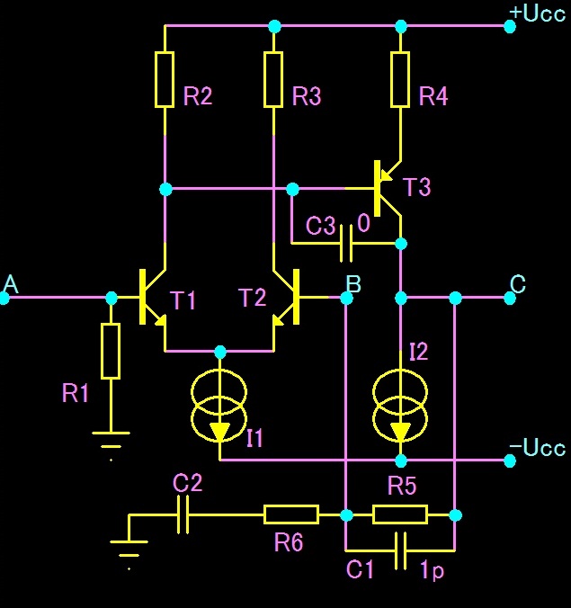
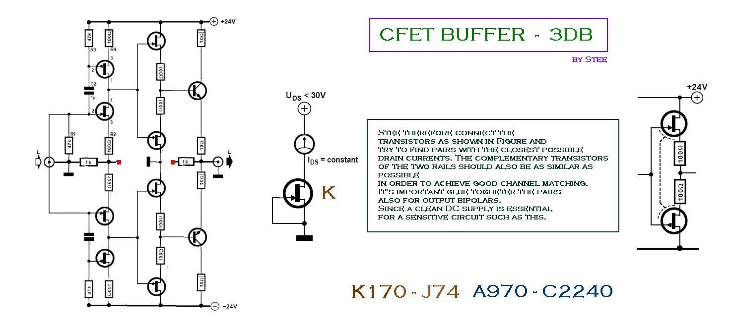
Stee Topology is extreme, it's only 1,4 degrees, Topology >>>CFET BUFFER<<< verified Photoshop SIMULATIONS!
Please click here --->http://www.diyaudio.com/forums/attachments/solid-state/150830d1261245600-jfet-audio-buffer-cfet-buffet.gif
Full Balance! ---> http://www.esafono.it/What do you think? 😕

Here is the SPICE
C:\USERS\BOBBY\DESKTOP\MODEL.CIR Transient Analysis
*
C1 C B 2P
C3 5 C 0
C4 0 10 10000U
C 2 0 100P
I1 11 -Ucc 8M
I2 C -Ucc 20M
QT1 5 A 11 BF422
QT2 6 B 11 BF422
QT3 C 5 7 BF421
R1 A 0 10K
R2 +Ucc 5 330
R3 +Ucc 6 330
R4 +Ucc 7 35
R5 B C 10K
R6 10 B 1111
R 1 2 100
V1 A 0 SIN (0 0 1K 0 0 0)
V2 13 0 PULSE (-1 1 1e-005 1e-006 1e-006 3.9e-005 0.0001)
V3 +Ucc 0 35
V4 0 -Ucc 35
VU 1 0 SIN (0 0 1K 0 0 0)
*
.MODEL T2 NPN ()
*** NPN High voltage transistors
.MODEL BF422 NPN (IS=25.1183F BF=1.98154K NF=998.408M VAF=100 IKF=279.922M
+ ISE=380.819F NE=1.37788 BR=1.16341 IKR=998.417M ISC=15.9121P NC=2.00133
+ RE=1.86192 RC=2 CJE=49.243P VJE=751.471M MJE=381.836M CJC=12.3409P
+ VJC=738.958M MJC=486.179M TF=2.55455N XTF=500M VTF=10 ITF=10.0019M TR=10N)
.MODEL BF421 PNP (
+ IS = 9.124E-15
+ NF = 0.9904
+ ISE = 1.672E-15
+ NE = 1.527
+ BF = 198.2
+ IKF = 0.13
+ VAF = 465.9
+ NR = 0.99
+ ISC = 2.139E-13
+ NC = 1.08
+ BR = 1.256
+ IKR = 0.1
+ VAR = 13
+ RB = 5
+ IRB = 1E-06
+ RBM = 0.5
+ RE = 0.635
+ RC = 1.42
+ XTB = 0
+ EG = 1.11
+ XTI = 3
+ CJE = 1.447E-11
+ VJE = 0.8484
+ MJE = 0.3884
+ TF = 1.38E-09
+ XTF = 21.78
+ VTF = 2
+ ITF = 0.065
+ PTF = 0
+ CJC = 8.483E-12
+ VJC = 0.6298
+ MJC = 0.4561
+ XCJC = 0.619
+ TR = 1E-32
+ CJS = 0
+ VJS = 0.75
+ MJS = 0.333
+ FC = 0.99)
*
.OPTIONS ACCT LIST OPTS ABSTOL=1pA CHGTOL=.01pC DEFL=100u DEFW=100u DIGDRVF=2
+ DIGDRVZ=20K DIGERRDEFAULT=20 DIGERRLIMIT=10000 DIGFREQ=10GHz DIGINITSTATE=0
+ DIGIOLVL=2 DIGMNTYMX=2 DIGMNTYSCALE=0.4 DIGOVRDRV=3 DIGTYMXSCALE=1.6 GMIN=1p
+ ITL1=100 ITL2=50 ITL4=10 PIVREL=1m PIVTOL=.1p RELTOL=1m TNOM=27 TRTOL=7 VNTOL=1u
+ WIDTH=80
*
.LIB "C:\MC7NET\LIBRARY\NOM.LIB"
*
.TEMP 27
.TRAN 2e-005 0.001 0
.PRINT TRAN (V([A])*10) V()
.PLOT TRAN (V([A])*10) V() -0.01,0.0025
.PROBE
*** Parts Count
** Battery 2
** Resistor 7
** Capacitor 4
** NPN 2
** PNP 1
** Pulse source 1
** Sine source 2
** Isource 2
.END
It seems you're saying that:
1: Phase shift between the input and output of an amplifier (NOT stereo phase shift) is bad.
2: That phase shift between input and output decreases the effectiveness of feedback because the two signals being compared are out of phase. Thus the NFB becomes preoccupied with phase, which it can't completely remove.
3: Tubes don't have this issue, guessing by the way you describe this distortion as "transistor sound".
Am I right?
Also, I don't know what you mean by "reserve profits". Could you use a different word or phrase?
I am interested and want to understand what you're saying.
- keantoken
It seems you're saying that:
1: Phase shift between the input and output of an amplifier (NOT stereo phase shift) is bad.
2: That phase shift between input and output decreases the effectiveness of feedback because the two signals being compared are out of phase. Thus the NFB becomes preoccupied with phase, which it can't completely remove.
3: Tubes don't have this issue, guessing by the way you describe this distortion as "transistor sound".
Am I right?
Also, I don't know what you mean by "reserve profits". Could you use a different word or phrase?
I am interested and want to understand what you're saying.
- keantoken
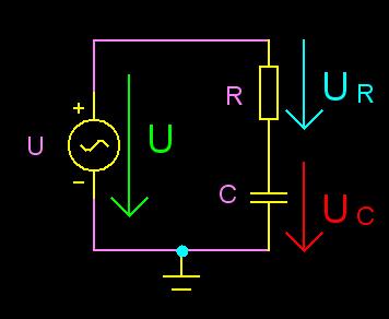
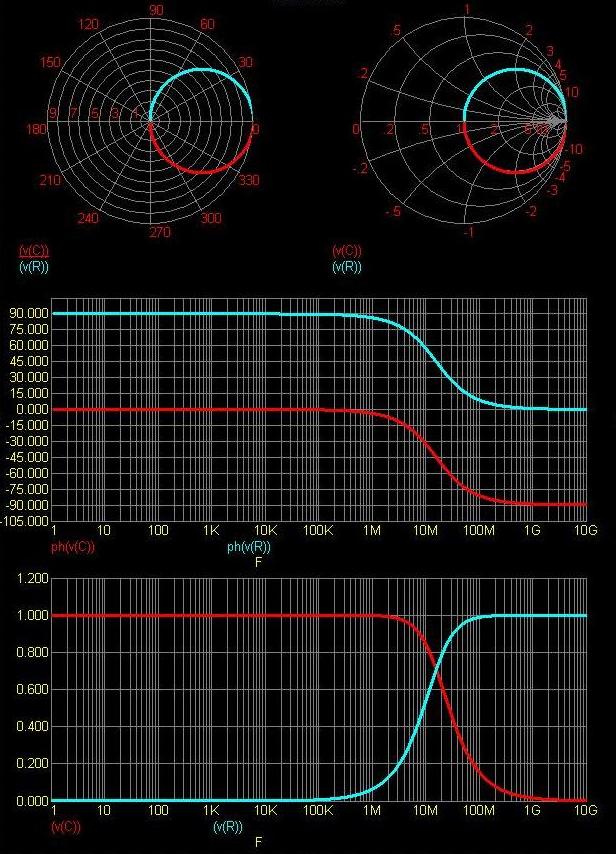
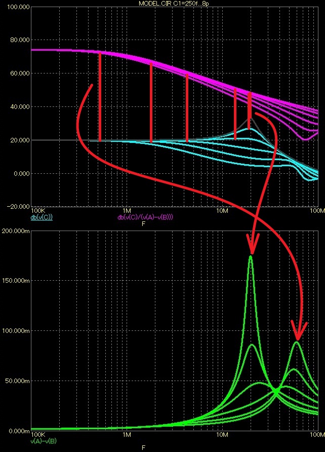
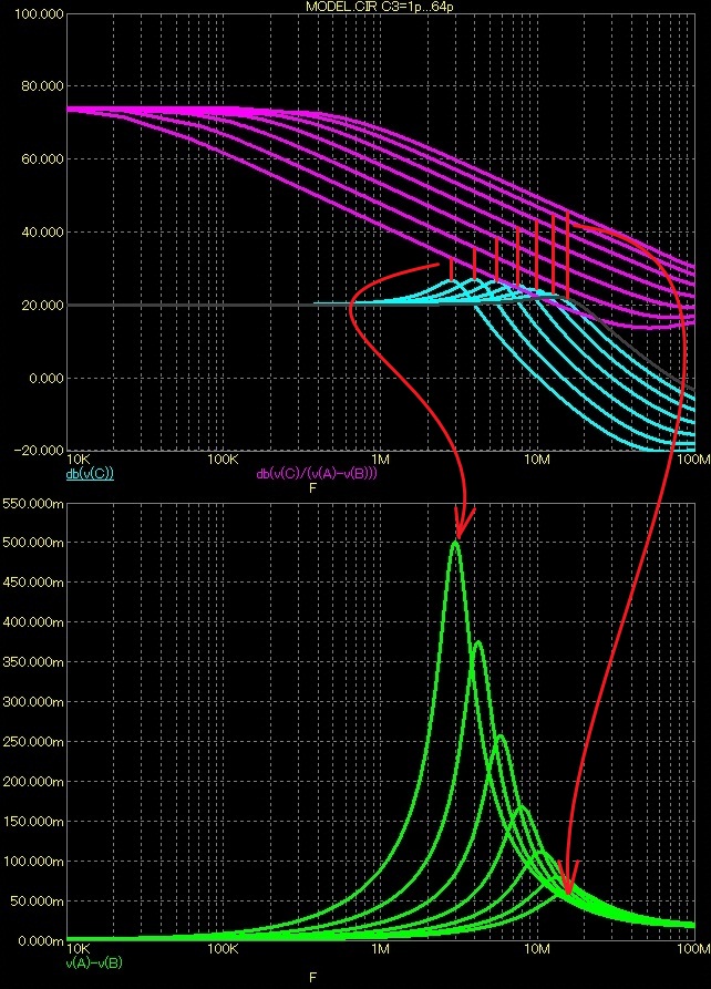
Vdif = v(A)-v(B) - Green
Output voltage = db(v(C)) - Blue
Amplification without feedback = Output voltage/Vdif = db(v(C)/(v(A)-v(B))) - Purple
Reserve gain= Amplification without feedback - Output voltage - Red vertical
For sinus:
Output voltage = Vdif * Amplification without feedback
The frequency is increasing, decreasing amplification without feedback, Vdif growing, increasing angle of rotation of the output signal. Rotation of the output signal gives a picture of the whole amplifier. Tubes have a lot MHz bandwidth, transistors no!
Overall feedback C1 0,25-0,5-1-2-4 to 8pF
Local feedback C3 1-2-4-8-16-32 to 64pF, + C1=1pF
Local feedback C3 1-2-4-8-16-32 to 64pF, + C1=1pF
Last edited:
Especially output transformers (needed ) in tube power amps..Tubes have a lot MHz bandwidth, transistors no!
Show us THD vs. frequency (measured!!) graph (or THD at 20kHz, or IMD19+20kHz) in one of many of your realized amps!
Your theory about as "big" as possible overal NFB is totaly wrong (known 30years), this caused "transistor" sound- stabiltity issues in real world (maybee not so in your simulations without output stages),saturation in very nonlinear stages,e.g bipolar difamp without degeneration, very short linear region, resistive loaded output of diffamp, VAS without buffer or other attempt to linearize it before feedback and many others mistakes..
Last edited:
Especially output transformers (needed ) in tube power amps..
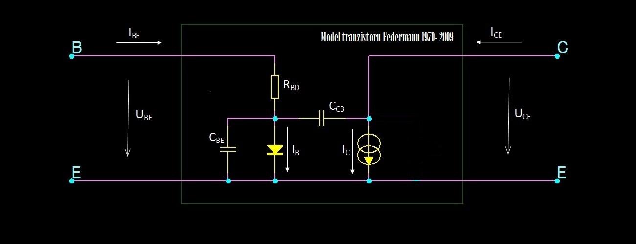
I'm talking about the tube and transistor, no talking about the whole amplifier. Tube has a much smaller RC constant as the transistor, I'm talking about. It can provide a rotation signal, the internal RC making decrease amplification. I'm not talking about what is also connected to the tube or transistor.
That is nice theory, Federmann....and practical results ? Never ending zero....
40 years of my amps have better sound than the DPA.
You are not talking....it is just practices, which you haven't...and it is quite different from theory....
😛😛, very interesting, wasn´t it so called "ínner sounds" heard by nobody , only you??40 years of my amps have better sound than the DPA.
Tubes-You can not (practicaly) realize power amp with tubes without output transformer. So talking about advantages in nonrealistic simulations is nonsense. So You can simulate audio power apmlifier with GaS Mosfets...Speedy enough??
And also much smaller output current, so transformer is innevitable..Tube has a much smaller RC constant as the transistor
Last edited:
😛😛, very interesting, wasn´t it so called "ínner sounds" heard by nobody , only you??
Tubes-You can not (practicaly) realize power amp with tubes without output transformer. So talking about advantages in nonrealistic simulations is nonsense. So You can simulate audio power apmlifier with GaS Mosfets...Speedy enough??
And also much smaller output current, so transformer is innevitable..
Join height - condenser speakers directly to the anode, then take the transformer only for low frequencies. RC is a constant, not dependent on the current is dependent on the physical characteristics of vacuum tubes and transistors.
He don´t know much more things.
For charging and discharging relatively big capacitance at high frequencies you must have enough current available...and adding such capacity to anode will change your R-C constant.Join height - condenser speakers directly to the anode,
- Status
- Not open for further replies.
- Home
- Amplifiers
- Solid State
- Influence of the delay amplifiers for listening characteristics