I think laminated iron bars is the better choice for the core.Solid iron VS laminated iron will make any difference in performance?
They will reduce the eddy currents.
Anyway, it was what I had in the shop; leftovers from a planar bass project.
Last edited:
A while back, I stumbled upon the ZF or Zeus amp doe to working on an inductive volume control project. Circlomanen tested the ZF many years ago and I was curious if he used that amplifier still.
He mentioned the SLAP(s) amplifiers and this is the first thread out of 4, that I have read through - very interesting amplifier.
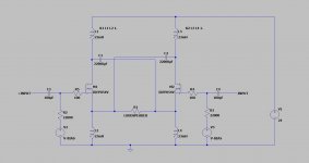
Just one question: Looking at the sch. there is only 1 Vinput, but the design is balanced. Is the 1 pcs Vinput a simulation thing and in reality one uses bot +V and -V for true balanced operation ?
He mentioned the SLAP(s) amplifiers and this is the first thread out of 4, that I have read through - very interesting amplifier.
Just one question: Looking at the sch. there is only 1 Vinput, but the design is balanced. Is the 1 pcs Vinput a simulation thing and in reality one uses bot +V and -V for true balanced operation ?
Yes, X-SLAPS is very interesting and unconventional and kind of the "end station" for the SLAPS technology - until Circlomanen comes up with a new bright idea!A while back, I stumbled upon the ZF or Zeus amp doe to working on an inductive volume control project. Circlomanen tested the ZF many years ago and I was curious if he used that amplifier still.
He mentioned the SLAP(s) amplifiers and this is the first thread out of 4, that I have read through - very interesting amplifier.
Just one question: Looking at the sch. there is only 1 Vinput, but the design is balanced. Is the 1 pcs Vinput a simulation thing and in reality one uses bot +V and -V for true balanced operation ?
Vin is just a label. The real input is V2, and V2+ and V2- are used for true balanced operation just as you suspected.
An externally hosted image should be here but it was not working when we last tested it.
I got a suggestion to use a cathodyn (a.k.a split load inverter).
But I cowardly walked away from that path.
The preamplifier is now a simple operational amplifier (OPA1612) with 11 times amplification (V2+) followed by an inverter (V2-).
I will exhibit the X-SLAPS together with SALS?A! in November at the diy meeting in Mölnlycke.
Thanks for the reply. If it were up to me, all amplifiers used balanced operation 🙂
Since I am working on a passive transformer based pre-amplifier, if the X-SLAPS need gain, then the gain stage need to be in the X-SLAPS itself. Perhaps a 1:11 step up transformer 🙂
A diy meet in Mölnlycke sounds interesting, if I can attend, I would be able to gaze upon your creation, share some thoughts and learn first hand from the creator 🙂 - I will check the thread you linked to.
Many thanks
Yes, that's a thought. Alas, I lack the knowledge on how to make a good one.Thanks for the reply. If it were up to me, all amplifiers used balanced operation 🙂
Since I am working on a passive transformer based pre-amplifier, if the X-SLAPS need gain, then the gain stage need to be in the X-SLAPS itself. Perhaps a 1:11 step up transformer 🙂
And, as the pre-amplifiers I have are in the same domain as the amplifiers in the DAC, I hesitate to introduce a signal level transformer as yet a domain.
Otherwise, you are of course welcome to visit me at my "shop" anytime. I live in Hyssna, 40 km southeast of Göteborg.A diy meet in Mölnlycke sounds interesting, if I can attend, I would be able to gaze upon your creation, share some thoughts and learn first hand from the creator 🙂 - I will check the thread you linked to.
Many thanks
I think it's best if the source is always at full line level output and then adjust the volume with an inductive volume control which is a constant power device opposite to resistors which are power converting and throw input away as heat,And, as the pre-amplifiers I have are in the same domain as the amplifiers in the DAC, I hesitate to introduce a signal level transformer as yet a domain.
in order to attenuate the the output - The results are less voltage AND current. To me, that is a form of compression.
The inductive type does not do that. As we attenuate the volume, the voltage goes down and the current as well as inductance goes up. The dynamics and micro-details are said to be very high for TVC based volume attenuation. 😀
A private introduction and possible listening session - tumanhand - I would not mind that at all - expect a PM 🙂Otherwise, you are of course welcome to visit me at my "shop" anytime. I live in Hyssna, 40 km southeast of Göteborg.
man that's some serious hardware there!
I don't care for hardware itself, I'm happy to see that amount of passion and work invested ...... meaning - I'm happy for you
Seriously Fugly!

I don't care for hardware itself, I'm happy to see that amount of passion and work invested ...... meaning - I'm happy for you
Seriously Fugly!
I have been following along just to marvel at the dedication it's taken to make this come to life. Congratulations, and thank you for sharing the journey and your video.
Thank you Zen Mod and ItsAllInMyHead.
Yes, it has been an intense summer.
By the way, when I was talking about putting them in the cupboards behind me, I meant hiding behind me.
The cupboards are actually in the attic as it is a sloping roof, so their dissipating heat will not disturb me and they will have it cooler.
And my listening room will be less cramped.
If you are in the vicinity of Gothenburg, Sweden, you can listen to these this Saturday ( 6th of November 2021).
I've just passed link to my close friend, living in Gothenburg
who knows, maybe he'll be interested ........ not exactly DIY person, but his entire amplification is made by me...... it counts in some way 🙂
who knows, maybe he'll be interested ........ not exactly DIY person, but his entire amplification is made by me...... it counts in some way 🙂
That would be great!I've just passed link to my close friend, living in Gothenburg
who knows, maybe he'll be interested ........ not exactly DIY person, but his entire amplification is made by me...... it counts in some way 🙂
If he decides to come, I'll be more than happy to play some amplifier shot out music of his. I'll PM you my mail address so that he can tell me.
I want to try balanced XSLAPS;
The calculation for single 23mH inductor as flollows;

For bifilar winding we have to double the values here above;
I was thinking if quadrifilar make sense or not?

Also in both bifilar and quadrilar winding there is 2 pin end output but we need 4 pin positive rail, negative rail, drain and source.
Could you please make a small sketch to explain it.
The calculation for single 23mH inductor as flollows;
For bifilar winding we have to double the values here above;
I was thinking if quadrifilar make sense or not?
Also in both bifilar and quadrilar winding there is 2 pin end output but we need 4 pin positive rail, negative rail, drain and source.
Could you please make a small sketch to explain it.
Attachments
L1 and L2 windings makes up one bifilar SLAPS coil.
L3 and L4 the other.
Both have four terminalrs: positive rail, negative rail, drain and source
L3 and L4 the other.
Both have four terminalrs: positive rail, negative rail, drain and source
As far as i know in bifilar winding the ends of 2 winding are connected each other.

if we seperate them they will be 2 solenoid winding. So Feedforward error correction effect winn no more i guess?
if we seperate them they will be 2 solenoid winding. So Feedforward error correction effect winn no more i guess?
Thanks than i will follow dot notations on the schematic. This is gonna be expensive 🙂The ends of the two windings are not connected to each other.
- Home
- Amplifiers
- Pass Labs
- Improving SLAPS - introducing X-SLAPS