I've a couple of threads about Circlomanen's SLAPS in the solid state section but I hope that I can get more responses in Pass Labs section as the SLAPS concept is both simple, unconventional and also involves single hot MOSFETs. That is, it's kinda Pass Labish.
I'm very pleased with the two incarnations's performance, especially when it comes to reproduce complex music.
But there is an unexplored cross-feed configuration that I'd like some input on - the X-SLAPS suggested by Circlomanen.
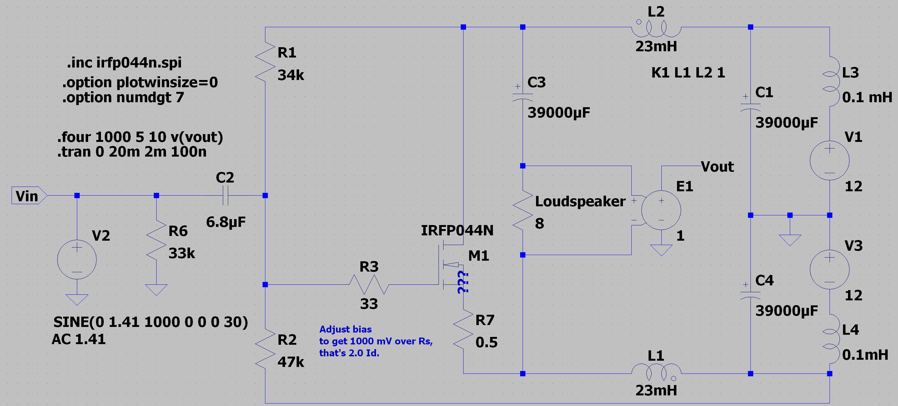
This is the single 4 W SLAPS:
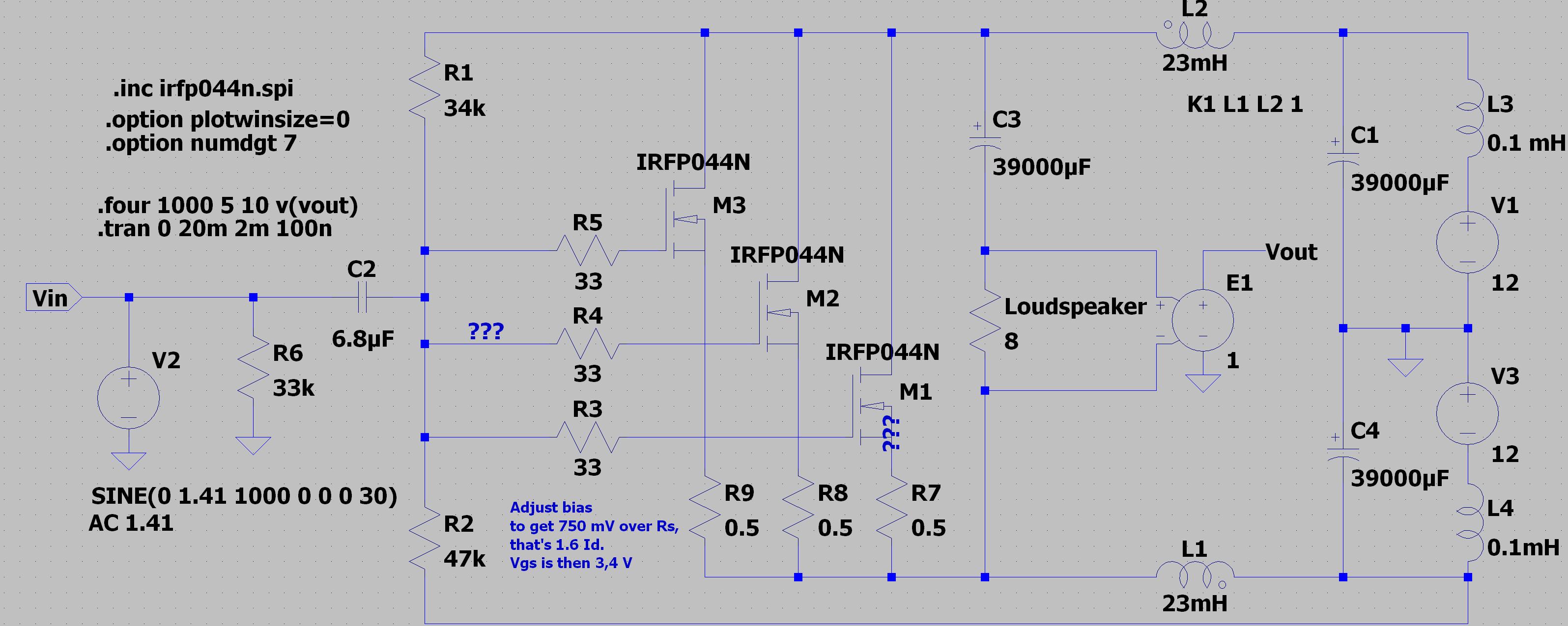
This is the triple 4 W SLAPS:
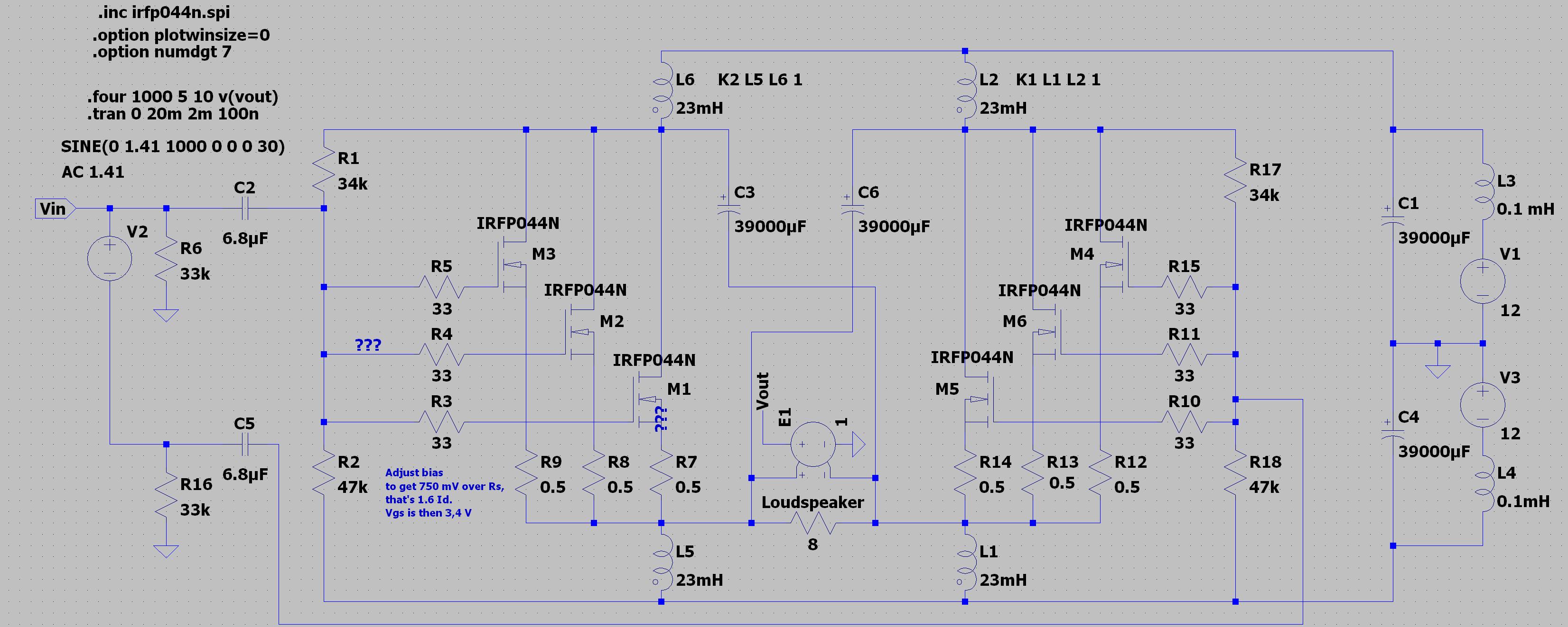
This is the triple 4 W X-SLAPS:
There's even a single 4 W X-SLAPS, you'll just have to imagine that M2,3,4 and 6 and their associated resistors are not there in the above schematic.
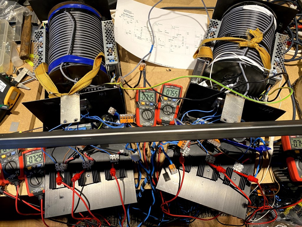
This is how the experimental hook up looks like for the triple 4 W X-SLAPS (don't bother about the steel profile across the picture, it belongs to another project of mine):
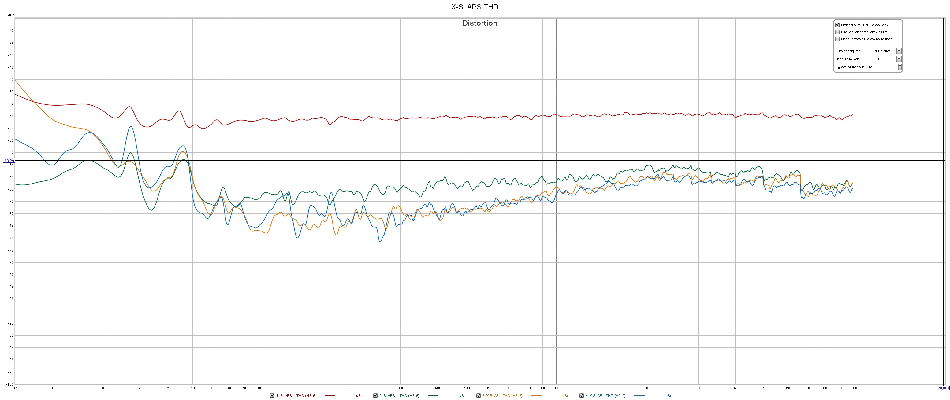
Now to my concerns about the 2nd and 3rd HD.
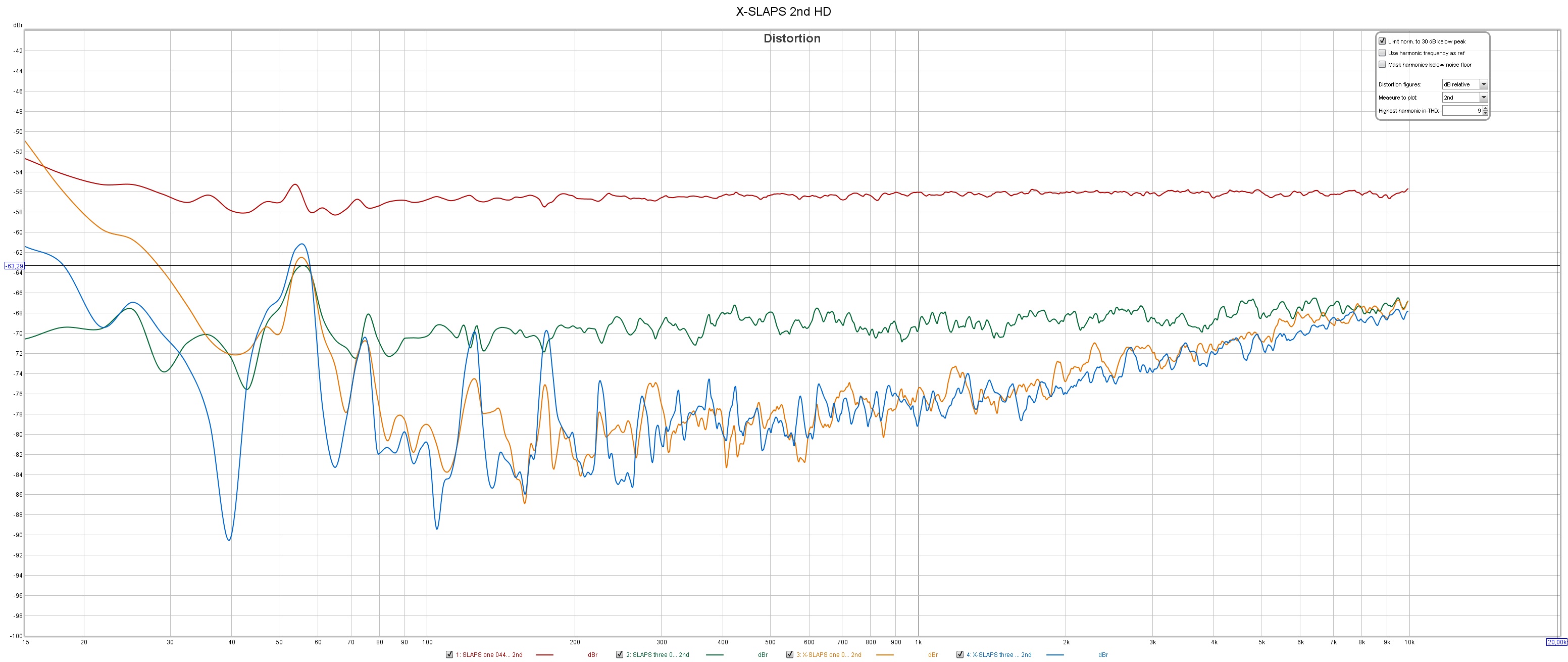
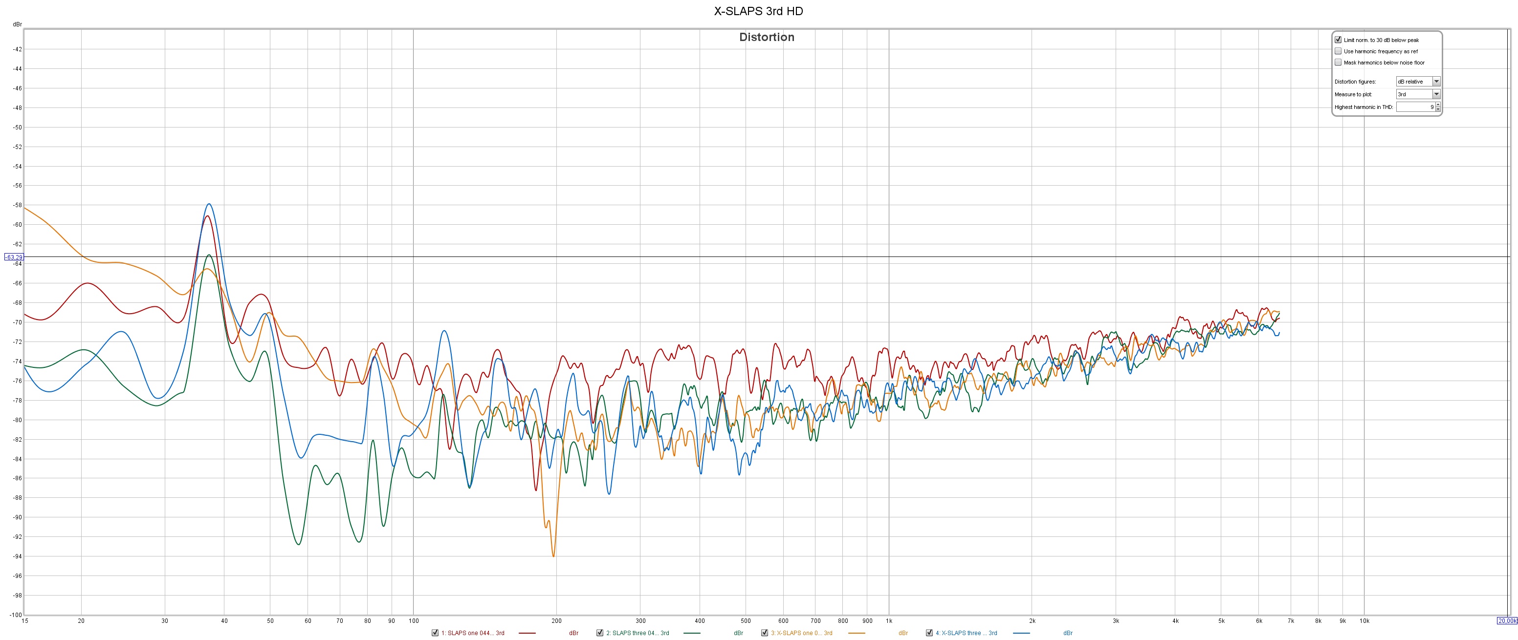
(Red - Single SLAPS, Teal - Triple SLAPS, Orange - Single X-SLAPS, Blue - Triple X-SLAPS)
THD:
2nd HD:
3rd HD:
The balance cancellation of the X-SLAPS improves the 2nd HD up 10 dB, but not the 3rd HD where it's only the Feed Forward Error Correction at work.
The Feed Forward Error Correction doesn't have the needed infinite inductance, so it falls off at lower frequencies.
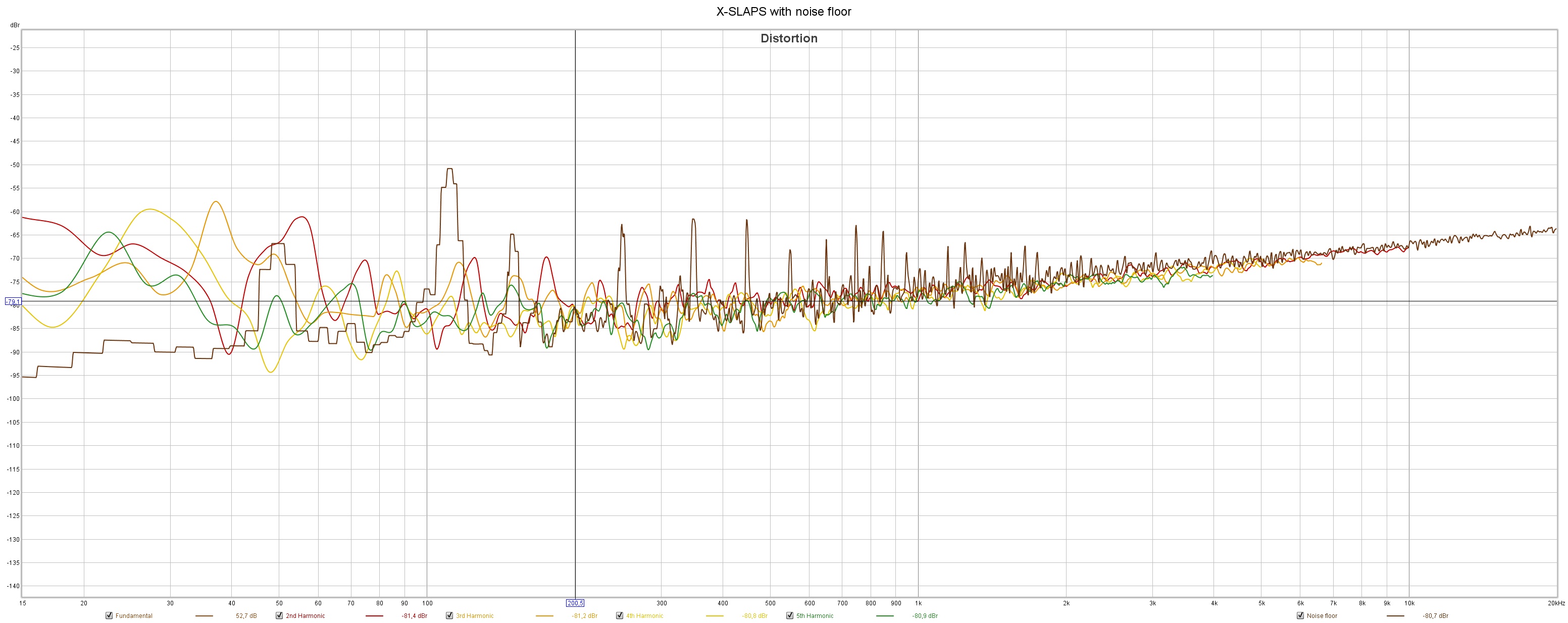
For the Triple X-SLAPS and above 200 Hz or so, we practically are in the noise floor (Brown) due to the SMPSs and measuring environment:
Any thoughts?
I'm very pleased with the two incarnations's performance, especially when it comes to reproduce complex music.
But there is an unexplored cross-feed configuration that I'd like some input on - the X-SLAPS suggested by Circlomanen.
This is the single 4 W SLAPS:
An externally hosted image should be here but it was not working when we last tested it.
This is the triple 4 W SLAPS:
An externally hosted image should be here but it was not working when we last tested it.
This is the triple 4 W X-SLAPS:
An externally hosted image should be here but it was not working when we last tested it.
There's even a single 4 W X-SLAPS, you'll just have to imagine that M2,3,4 and 6 and their associated resistors are not there in the above schematic.
This is how the experimental hook up looks like for the triple 4 W X-SLAPS (don't bother about the steel profile across the picture, it belongs to another project of mine):
Now to my concerns about the 2nd and 3rd HD.
(Red - Single SLAPS, Teal - Triple SLAPS, Orange - Single X-SLAPS, Blue - Triple X-SLAPS)
THD:
An externally hosted image should be here but it was not working when we last tested it.
2nd HD:
An externally hosted image should be here but it was not working when we last tested it.
3rd HD:
An externally hosted image should be here but it was not working when we last tested it.
The balance cancellation of the X-SLAPS improves the 2nd HD up 10 dB, but not the 3rd HD where it's only the Feed Forward Error Correction at work.
The Feed Forward Error Correction doesn't have the needed infinite inductance, so it falls off at lower frequencies.
For the Triple X-SLAPS and above 200 Hz or so, we practically are in the noise floor (Brown) due to the SMPSs and measuring environment:
An externally hosted image should be here but it was not working when we last tested it.
Any thoughts?
Last edited:


I simplified the schematics to show the general function without all the clutter needed for a simulation.
The SLAPS design is a split load phase splitter based amp. It has a single ended input but a balanced and floating (not coupled to ground) output.
To get rid of the current surges and noise the highly reactive loudspeaker couples into the ground is a real improvment for sound quality and amp stability, and that is something that anyone using a SoZ design can attest to. Ground is supposed to be this black hole with zero resistance and impedance - able to sink any currunt instantly without ever moving away from 0.0000000000000000000 volts. Being the reference for everything in the amplifier it is important that ground is never unstable in being the perfect black hole sink for any and all currents. But real life ground is very far from this perfect theoretical black hole. It always have a resistance and will always be noisy and unstable to some extant. This is why I find that freeing the groundplane from the loudspeaker is such a boost for sound quality.
The closely coupled bifilar winded choke does add something close to Nelson Pass Super Symmetry. A form of simple Feed Forward Error Correction. And in my experience Super Symmetry and Feed Forward Error Correction does make an amp sound much better then normal negative feedback as a distortion canceling mechanism. This amp has a simulated -3 dB point at 2,5 Mhz without any traces of phase problems and hf instability. I guess real life performance is worse then this, but I do expect a realy stable and lightningfast amp (which is what we have experienced so far).
The XSLAPS is the first improvement to the SLAPS design I have been able to come up with in the years since the available sound quality of my first SLAPS torpedoed my intrest in developing any other amplifier.
Thanks for building the SLAPS designs and testing them.
Have you had a chance to listen to the XSLAPS driving a loudspeaker?
I don´t expect the 10 dB reduction in THD to make a large difference in sound quality alone, but the fully balanced design and the closly coupled twin parallel Feed Forward Error Correction should work wonders for the cancelation of even harmonics and for the control of the loudspeaker. It should in theory be a very stable platform for the Mosfets to acheive a very good control of the loudspeaker while driving this highly reactive load with very complex non sinusoidal signals (music).
Thank you for supplying us with such ingenius designs!
View attachment 899875
snip
Have you had a chance to listen to the XSLAPS driving a loudspeaker?
snip
No, as I have an active system there are a lot of amplifiers to rebuild.
As a short cut though, I was thinking of not drive the four sub-woofers with SLAPS or X-SLAPS.
Only the drivers for the tweeters, mids and woofers will then have to be rebuild.
If I do the rebuild all together that is.
Yes, but I'm still hoping that this forum can come up with something to reduce the 3rd HD...View attachment 899875
snip
I don´t expect the 10 dB reduction in THD to make a large difference in sound quality alone, but the fully balanced design and the closely coupled twin parallel Feed Forward Error Correction should work wonders for the cancellation of even harmonics and for the control of the loudspeaker. It should in theory be a very stable platform for the Mosfets to achieve a very good control of the loudspeaker while driving this highly reactive load with very complex non sinusoidal signals (music).
snip
come up with something to reduce the 3rd
There are always the dumb brute force approaches to lowering distortion. More current. Better coils. More linear devices etc etc...
With sufficiently many turns of magnetwire you will increase the inductance of the coils and make the coupling of the the bifilar windings better for a better Feed Forward Error Correction. With more current through more devices you will lower THD which includes the 3 harmonic content. The XSLAPS will due to the balanced design and the even harmonic cancelation always have more third harmonic then second harmonic. You can add second harmonic by making the balansed amp less well balanced. Use IRFP054 on one side and IRFP240 on the other. This will probably increase the distortion quite a bit. Not only add some nice and well behaved second harmonic asymmetry to the signal.
I do think that the XSLAPS does add qualities not easily seen in simulation though. The balansed design should in theory be better at controling the very nonlinear and reactive behaviour of the drivers. The balansed design and X coupled load should iron out a lot of the inherent defects of the active devices (of which the cancelation of second harmonics is the most easily seen in simulation and steady state THD measurments).
I would love to have the equipment to be able to accuratly measure the amps behaviour when imposing a short burst of highly transient and highly non-sinusoidal signal while the amp is busy driving a real life loudspeaker at high volume. To be able to take a short burst snapshot of the amp behaviour and not having to have a stable and quite start and stop. But to superimpose this in the middle of a large classical music crescendo when the drivers are working hard and not centered properly by their suspensions. This would say much more about the amp then driving a steady state sine wave across a non reactive power resistor.
A bass reflex box at full swing trying to reproduce real life music is a quite chaotic contraption. All the stored energy in the passive crossover parts, bellmodes of the cone and suspentions, enclosure walls, bass reflex port etc etc working togheter to make life a living hell for the amplifier.
I do find your pronounced peaks in the THD graph quite interesting. It does seem like the coils pick up some disturbances from the power supplies. Have you tried to place the coils in the opposite direction from each other? The distortion drops quite substantially over a quite large area of the graph but almost nothing in some small recurent peaks. This indicates some kind of interference or outside noise being recieved by the coils. I do suspect the switched mode power supplies......
The simplest way to lower third harmonic would probably be by increasing the voltage over the devices. If both sides gets more linear with a less pronounced assymetry (second harmonic) this will not be superimposed on the signal as a symmetrical (equal on both the positive and negative side of the signal) deviation from the orginal signal.
I do believe that a different device with a more triody transfer curve could be used. Test IRFPS3810 as a good example.
Even cascoding could be used to linearize each side of the XSLAPS circuit.
These are some thoughs and ideas I had while driving a few hours.
I do believe that a different device with a more triody transfer curve could be used. Test IRFPS3810 as a good example.
Even cascoding could be used to linearize each side of the XSLAPS circuit.
These are some thoughs and ideas I had while driving a few hours.
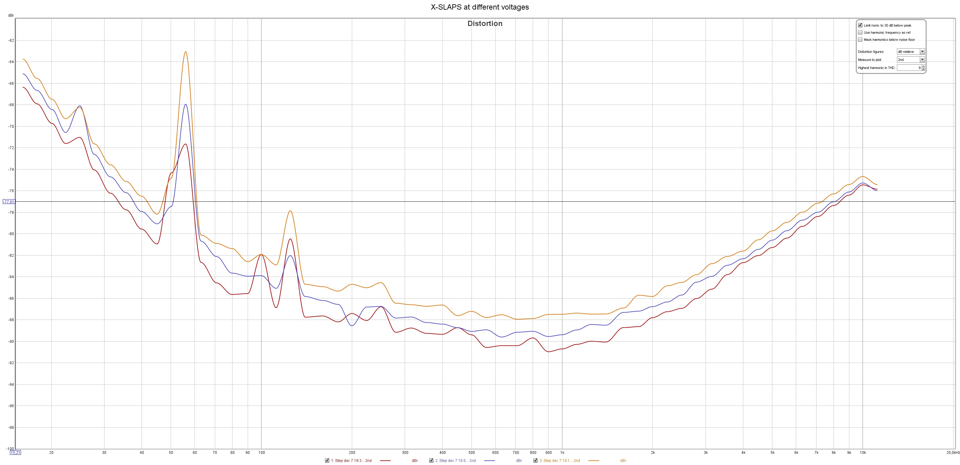
I tried with three voltages with the three aside X-SLAPS; +/- 11 V, +/- 12 V and +/- 13 V with the same Id 1.6 A.
No significant changes for 3rd HD but for 2nd HD it looked like this:
(Red: +/- 11 V, Blue +/- 12 V and Orange +/- 13 V)
So approximately one dBs difference with +/- 11 V as the "winner".
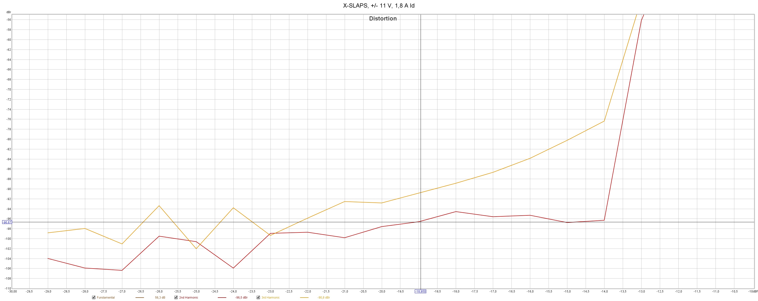
At +/- 11 V I get about 8 W before the distortion levels rises, I guess there's some clipping.
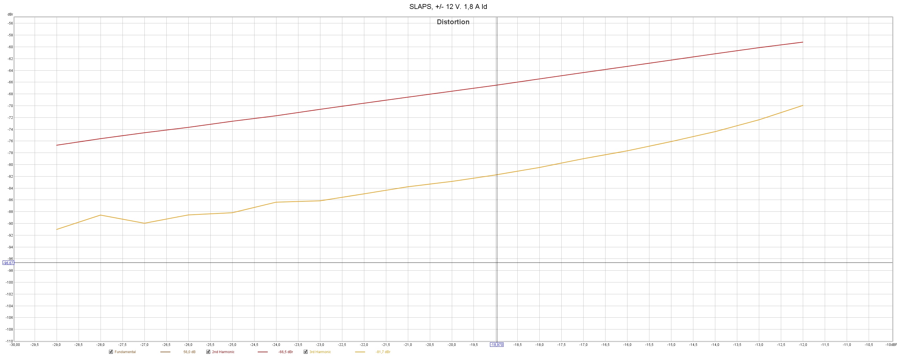
But at lower voltages the Id can be increased to have the same power dissipation, so I increased Id to 1.8 A for +/- 11 V and did some step level measurement at 1 kHz.
-29 dB in equals 0.25 W out and -12 dB equals 13 W out.
Over -12 dB I guess that the input clips.
Red is 2nd HD and orange is 3rd HD.
X-SLAPS +/- 11 V, Id 1.8 A:
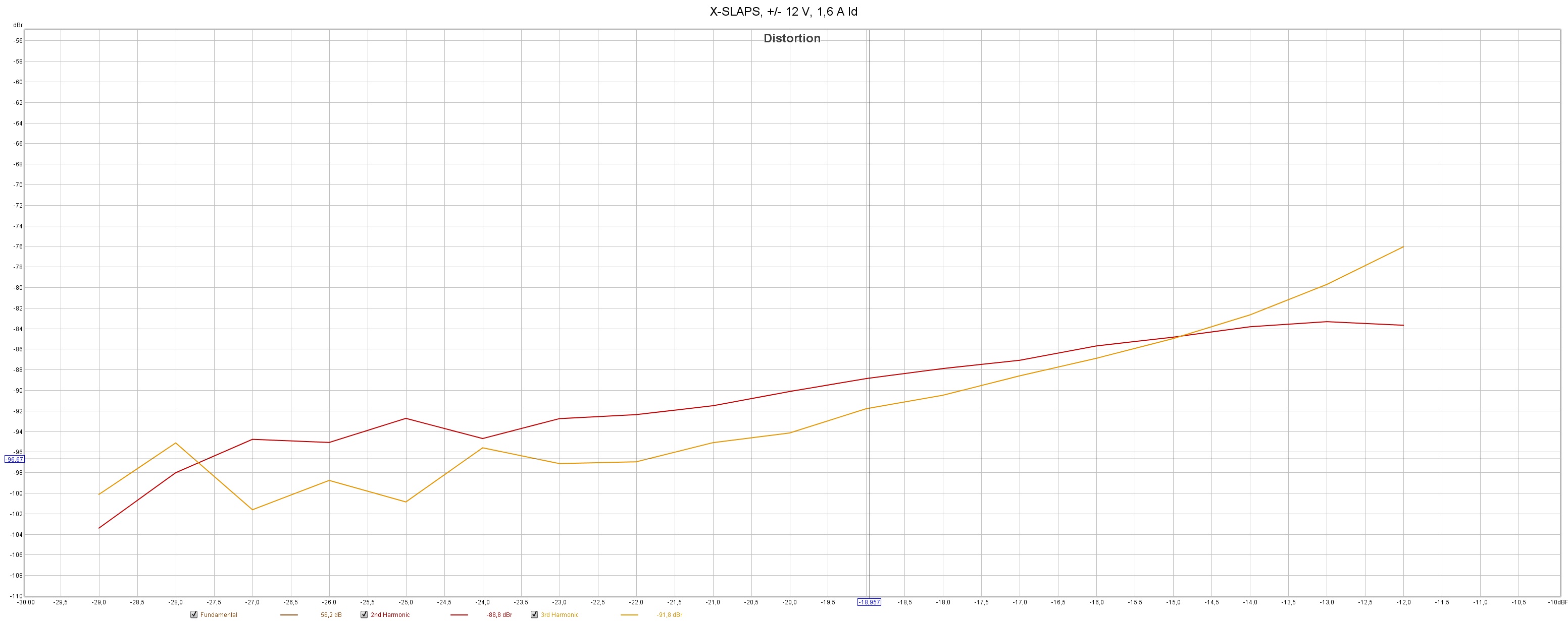
X-SLAPS +/- 12 V, Id 1.6 A:
Again, the 2nd HD is lowered a lot but the 3rd HD is more or less inaffected.
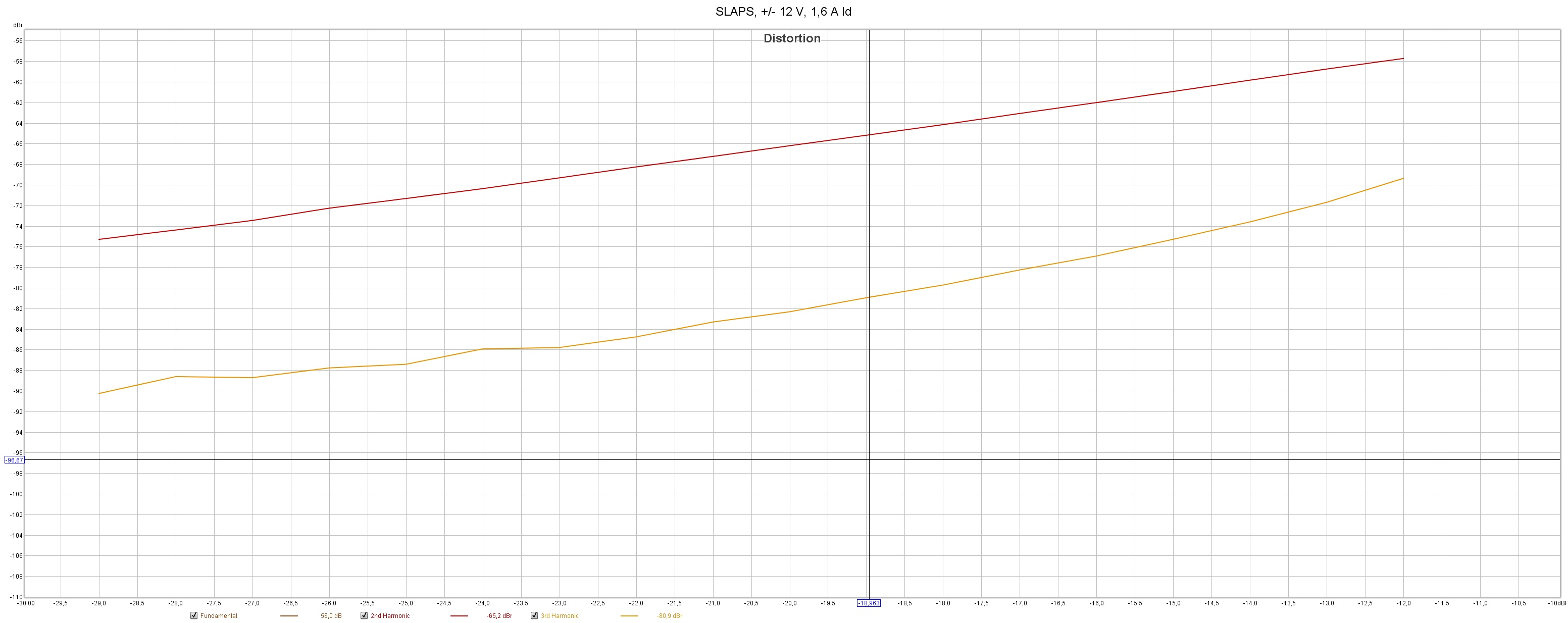
As a comparison, here's how SLAPS measures with two different Id, not much difference:
SLAPS+/- 12 V, Id 1.6 A:
SLAPS +/- 12 V, Id 1.8 A:
So what's the conclusion?
Well, the X-SLAPS configuration is really effective for even harmonics.
But there's no meaning to have the even HDs lower than the odd HDs as I see it.
So I will pursue with X-SLAPS with one MOSFET aside, at the cost of an extra SLAPS coil of course.
It'll be easier to match the devices with only one aside and I can probably raise the Id a lot with the same heat sink.
I will of course also test with IRFPS3810.
No significant changes for 3rd HD but for 2nd HD it looked like this:
(Red: +/- 11 V, Blue +/- 12 V and Orange +/- 13 V)
An externally hosted image should be here but it was not working when we last tested it.
So approximately one dBs difference with +/- 11 V as the "winner".
At +/- 11 V I get about 8 W before the distortion levels rises, I guess there's some clipping.
But at lower voltages the Id can be increased to have the same power dissipation, so I increased Id to 1.8 A for +/- 11 V and did some step level measurement at 1 kHz.
-29 dB in equals 0.25 W out and -12 dB equals 13 W out.
Over -12 dB I guess that the input clips.
Red is 2nd HD and orange is 3rd HD.
X-SLAPS +/- 11 V, Id 1.8 A:
An externally hosted image should be here but it was not working when we last tested it.
X-SLAPS +/- 12 V, Id 1.6 A:
An externally hosted image should be here but it was not working when we last tested it.
Again, the 2nd HD is lowered a lot but the 3rd HD is more or less inaffected.
As a comparison, here's how SLAPS measures with two different Id, not much difference:
SLAPS+/- 12 V, Id 1.6 A:
An externally hosted image should be here but it was not working when we last tested it.
SLAPS +/- 12 V, Id 1.8 A:
An externally hosted image should be here but it was not working when we last tested it.
So what's the conclusion?
Well, the X-SLAPS configuration is really effective for even harmonics.
But there's no meaning to have the even HDs lower than the odd HDs as I see it.
So I will pursue with X-SLAPS with one MOSFET aside, at the cost of an extra SLAPS coil of course.
It'll be easier to match the devices with only one aside and I can probably raise the Id a lot with the same heat sink.
I will of course also test with IRFPS3810.
Last edited:
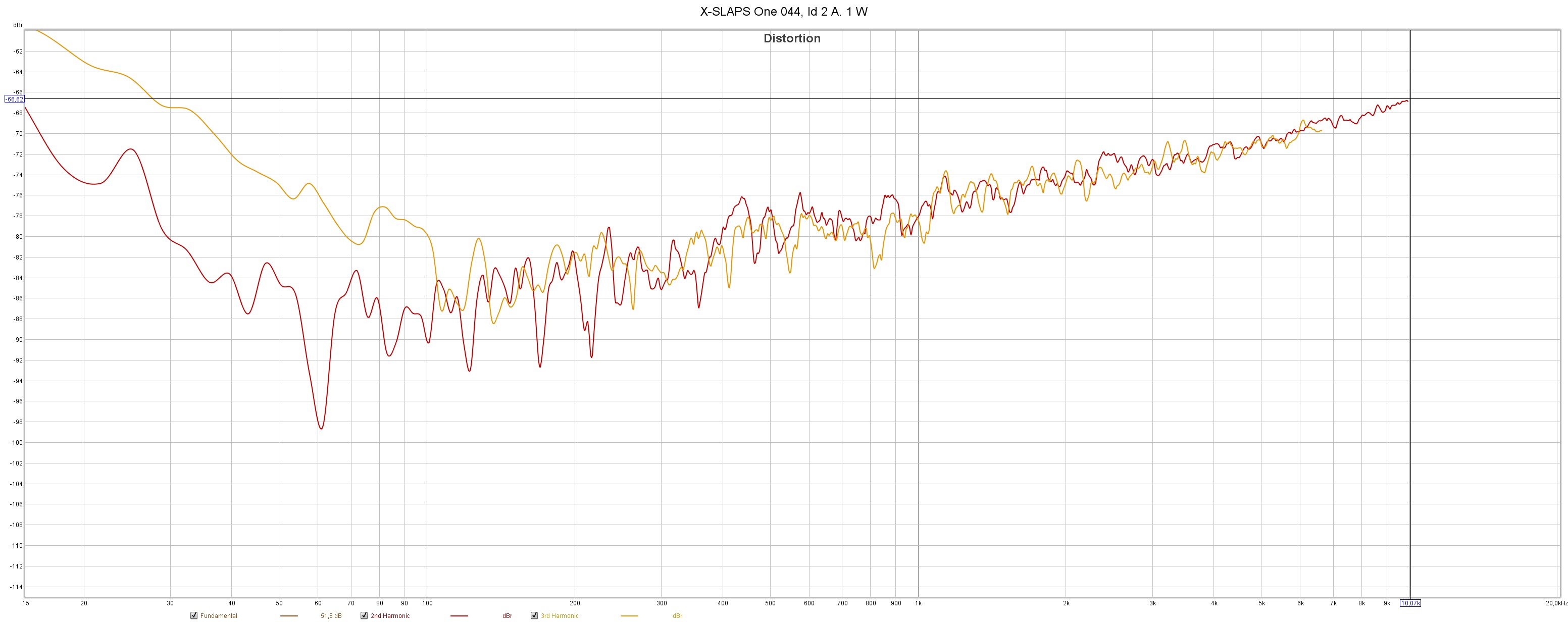
Single X-SLAPS with IRFP044 versus IRFPS3810.
Red is 2nd HD, orange is 3rd HD.
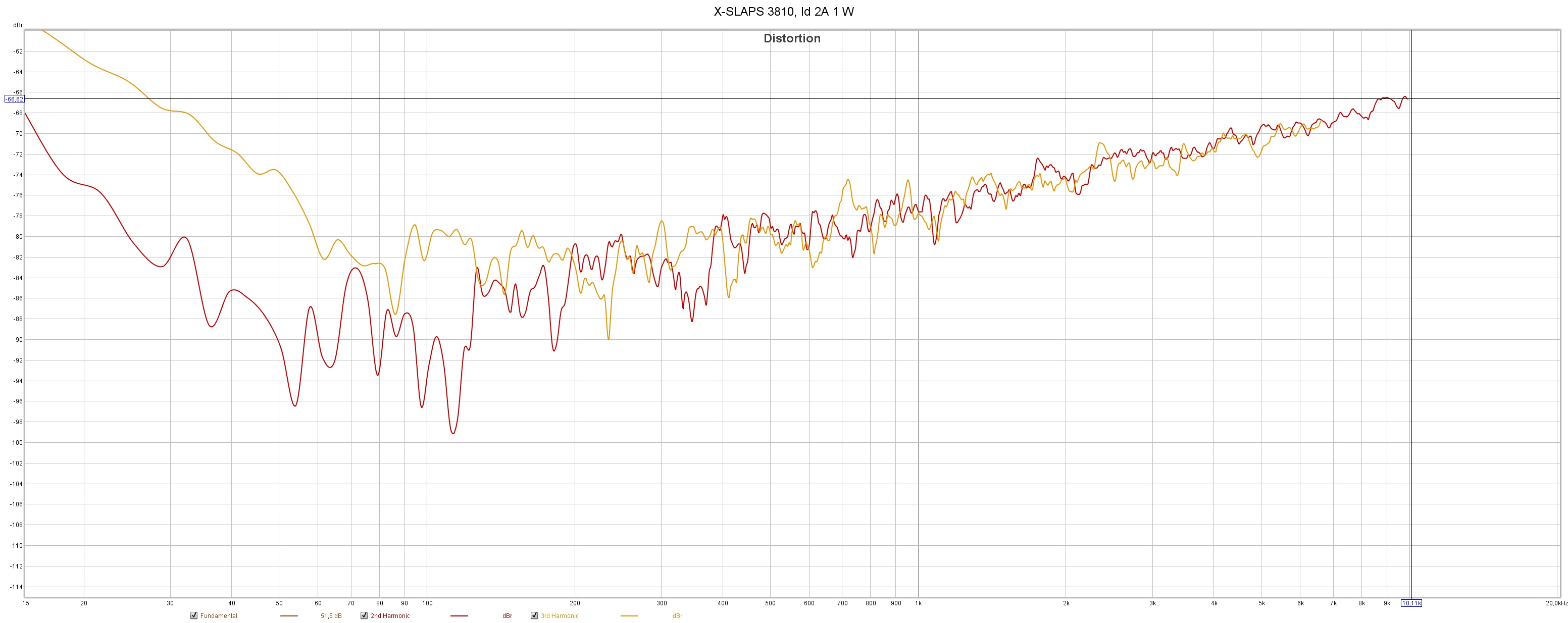
1 W IRFP044, Id 2A:
1 W IRFPS3810, Id 2A:
Not much difference.
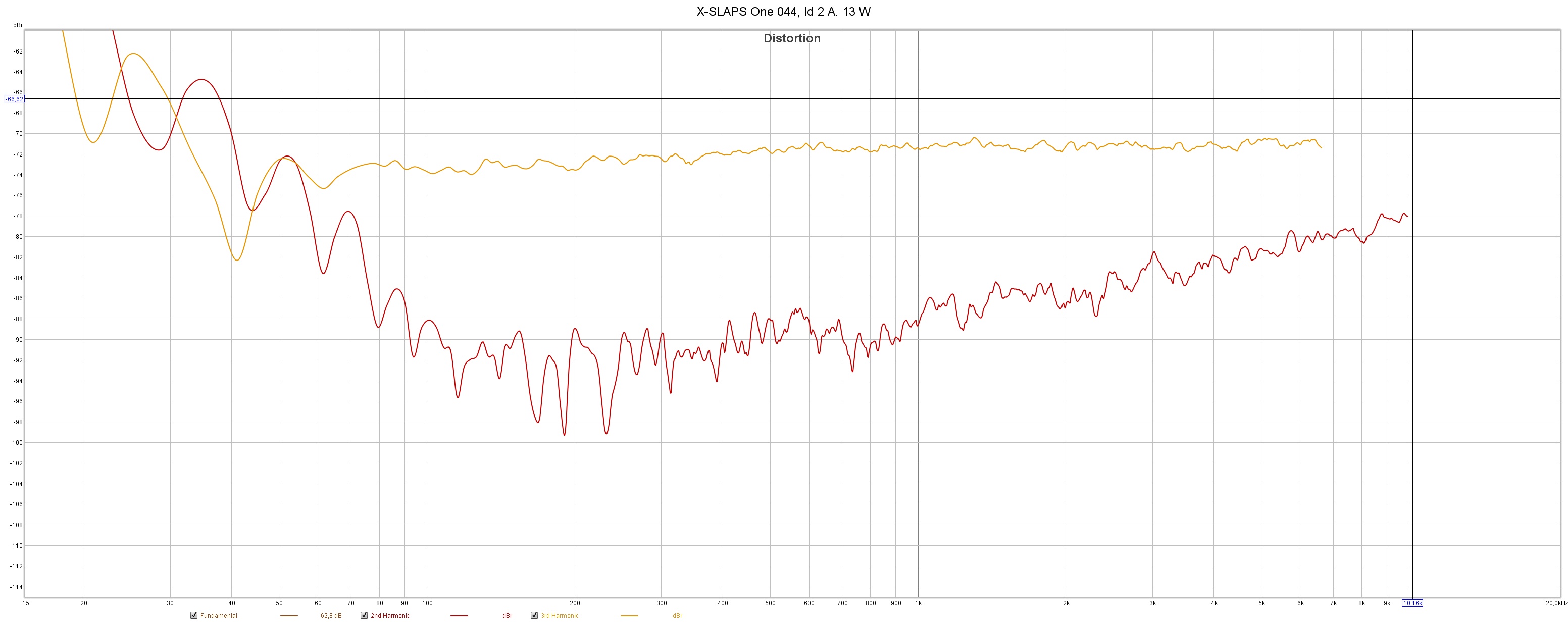
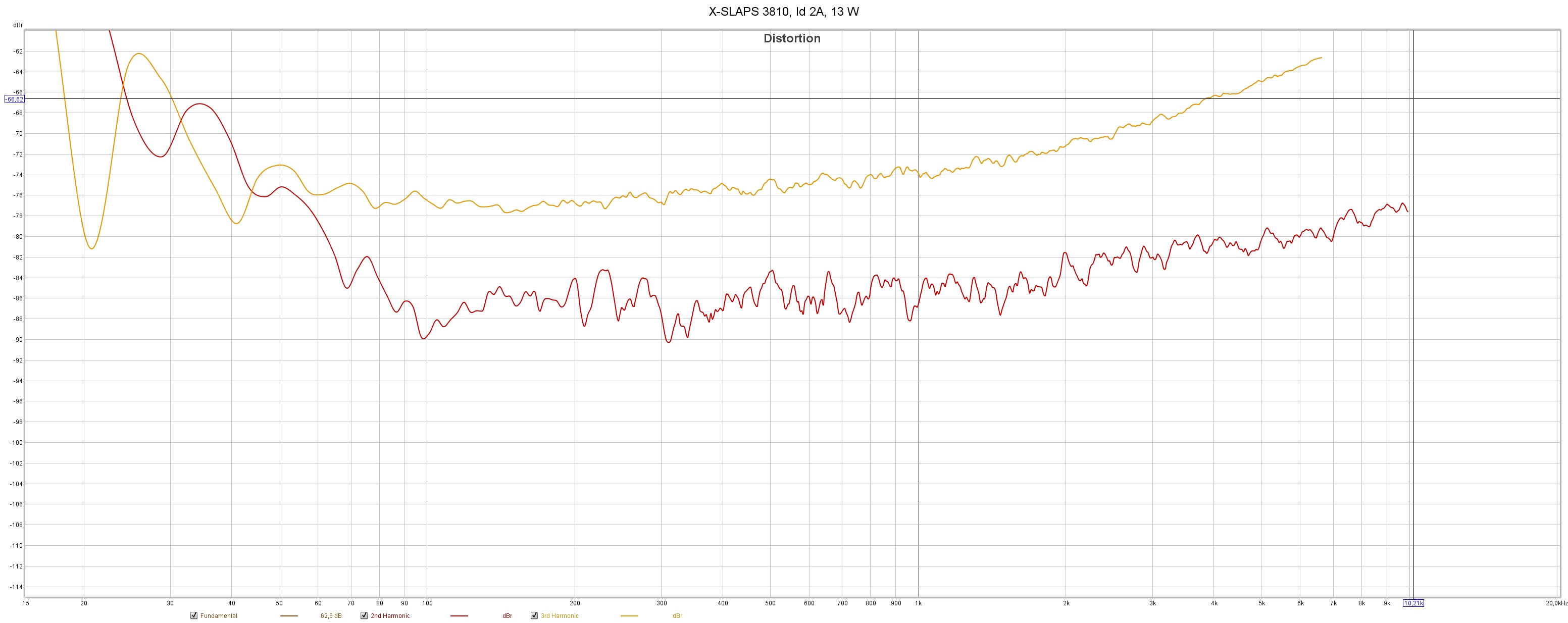
13 W IRFP044, Id 2A:
13 W IRFPS3810, Id 2A:
Even though the 2nd HD is higher for IRFPS3810, the 3rd HD is overall much lower!
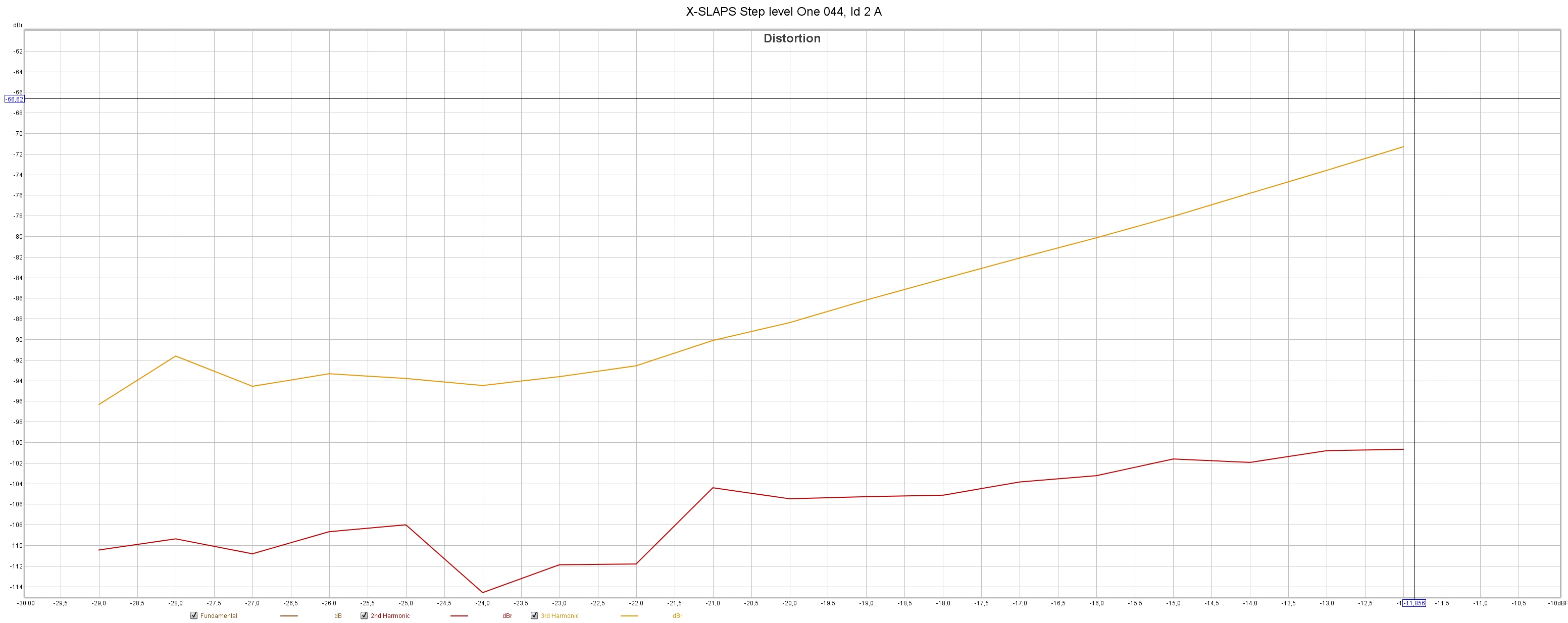
Step input level at 1 kHz:
IRFP044, Id 2A:
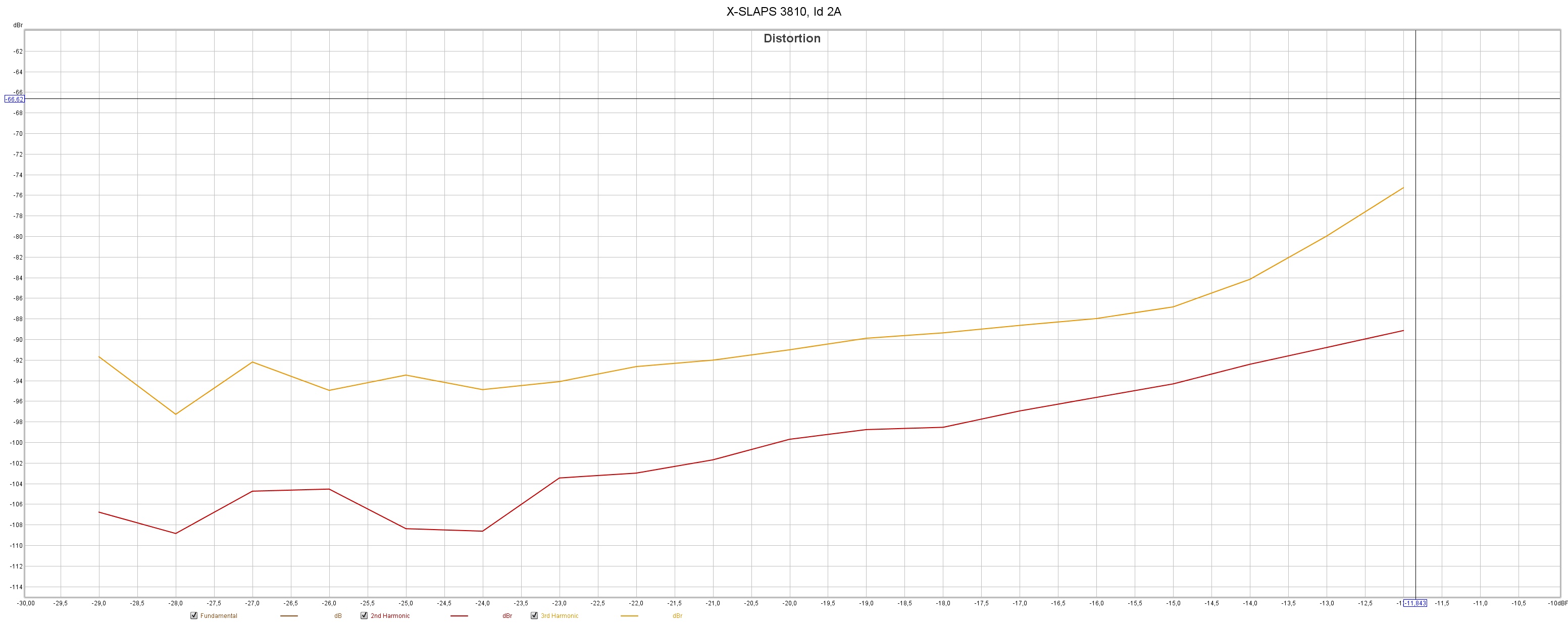
IRFPS3810, Id 2A
This also shows that even though the 2nd HD is higher for IRFP3810, the 3rd HD is overall much lower!
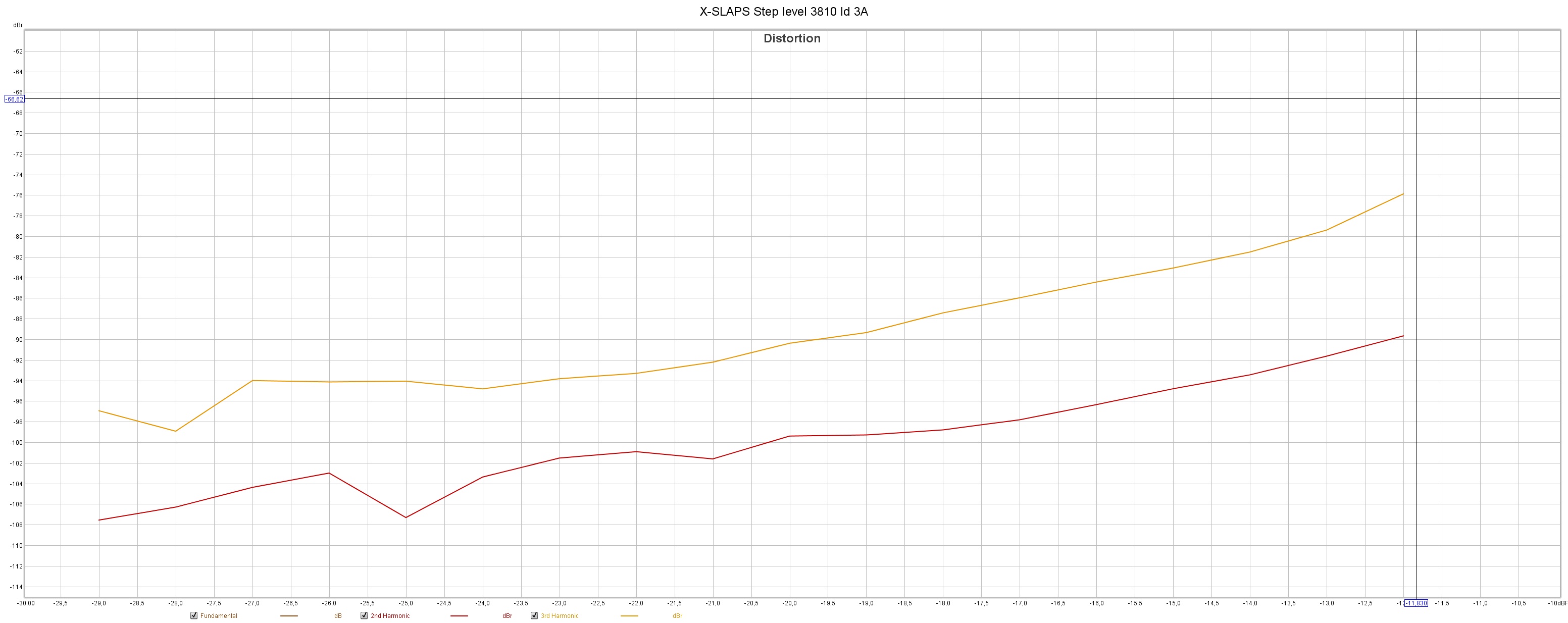
IRFPS3810, Id 3A
Not much difference from Id 2A.
I tried to separate the SLAPS coils a little bit, but with no change.
Red is 2nd HD, orange is 3rd HD.
1 W IRFP044, Id 2A:
An externally hosted image should be here but it was not working when we last tested it.
1 W IRFPS3810, Id 2A:
An externally hosted image should be here but it was not working when we last tested it.
Not much difference.
13 W IRFP044, Id 2A:
An externally hosted image should be here but it was not working when we last tested it.
13 W IRFPS3810, Id 2A:
An externally hosted image should be here but it was not working when we last tested it.
Even though the 2nd HD is higher for IRFPS3810, the 3rd HD is overall much lower!
Step input level at 1 kHz:
IRFP044, Id 2A:
An externally hosted image should be here but it was not working when we last tested it.
IRFPS3810, Id 2A
An externally hosted image should be here but it was not working when we last tested it.
This also shows that even though the 2nd HD is higher for IRFP3810, the 3rd HD is overall much lower!
IRFPS3810, Id 3A
An externally hosted image should be here but it was not working when we last tested it.
Not much difference from Id 2A.
I tried to separate the SLAPS coils a little bit, but with no change.
The IRFPS3810 seems like a welcome improvement in the distribution of harmonics over the IRFP044.
It is quite nice that the measured distortion does not improve substantially with more current. It does make it easier to justify running the amps slightly cooler.
The rising THD with rising frequency does probably come from a larger and less linear gate capacitance of the IRFPS3810.
I do like the sound character that I get from running IRFPS3810 in simple single end designs. It does have a nice "triody" character, and I guess this is more pronounced at lower currents (which is indicated by the lack of improvement at higher currents). Have you tried to parallell a few per side? It is nice to see that this translates to lower third harmonics in the XSLAPS design.
The IRFPS3810 seems like a welcome improvement in the distribution of harmonics over the IRFP044.
It is quite nice that the measured distortion does not improve substantially with more current. It does make it easier to justify running the amps slightly cooler.
The rising THD with rising frequency does probably come from a larger and less linear gate capacitance of the IRFPS3810.
I do like the sound character that I get from running IRFPS3810 in simple single end designs. It does have a nice "triody" character, and I guess this is more pronounced at lower currents (which is indicated by the lack of improvement at higher currents). Have you tried to parallel a few per side? It is nice to see that this translates to lower third harmonics in the XSLAPS design.
Yes, but again the IRFPS3810 proved to be a little bit unstable; after fifteen minutes or so playing in my setup, the current suddenly rose.
I had to shut it down when I smelled the ooze of the plastic around source resistor.
XSLAPS is now at such good HD levels that I'll go for IRFP044 for this application.
I haven't tried IRFPS3810 with more than one a side but my experience from "SLAPS for bass" isn't good when it comes to having more than one IRFPS3810 a side.
My main goal with XSLAPS is to lower the power consumption while keeping or improving the distortion levels for SLAPS.
I will later on also try XSLAPS with "SLAPS for bass" with IRFP150 and the +/- 24 V power supply.
I am convinced though that it will show the same improvements as IRFP044 at +/- 12V have done.
I must also build a new ten channel pre-amplifier with differential outputs since my setup is active with ten separate loudspeakers driven by an eight channel DAC.
I also have nine SLAPS coils to wind.

One thing that I am absolutely sure of is that SLAPS and XSLAPS by far exceeds the threshold of originality for a patent application.
The IRFPS3810 seems like a welcome improvement in the distribution of harmonics over the IRFP044.
It is quite nice that the measured distortion does not improve substantially with more current. It does make it easier to justify running the amps slightly cooler.
The rising THD with rising frequency does probably come from a larger and less linear gate capacitance of the IRFPS3810.
I do like the sound character that I get from running IRFPS3810 in simple single end designs. It does have a nice "triody" character, and I guess this is more pronounced at lower currents (which is indicated by the lack of improvement at higher currents). Have you tried to parallel a few per side? It is nice to see that this translates to lower third harmonics in the XSLAPS design.
Yes, but again the IRFPS3810 proved to be a little bit unstable; after fifteen minutes or so playing in my setup, the current suddenly rose.
I had to shut it down when I smelled the ooze of the plastic around source resistor.
X-SLAPS is now at such good HD levels that I'll go for IRFP044 for this application.
I haven't tried IRFPS3810 with more than one a side but my experience from "SLAPS for bass" isn't good when it comes to having more than one IRFPS3810 a side.
My main goal with X-SLAPS is to lower the power consumption while keeping or improving the distortion levels for SLAPS.
I will later on also try X-SLAPS with "SLAPS for bass" with IRFP150 and the +/- 24 V power supply.
I am convinced though that it will show the same improvements as IRFP044 at +/- 12V have done.
I must also build a new ten channel pre-amplifier with differential outputs since my setup is active with ten separate loudspeakers driven by an eight channel DAC.
I also have nine SLAPS coils to wind.
One thing that I am absolutely sure of is that SLAPS and X-SLAPS by far exceeds the threshold of originality for an patent application.
I am therefore surprised that posting this in the Pass Labs section of diyaudio hasn't generated more responses, except for you Circlomanen of course being the inventor.
Last edited:
I had a thought on the X-SLAPS. Would there be an advantage to Quatrafilar wind the inductor(s)? If I understand correctly, if the polarities were correct, you should get correction between sides as well as top / bottom.
Do not mistake lack of comments for lack of interest.
Thanks for sharing.
Do not mistake lack of comments for lack of interest.
Thanks for sharing.


After a few hours in LTSpice and a few hours more of searching online for x coupled transformer output stages I found the McIntosh unity gain transformer output circuit. The XSLAPS is pretty close, even though it is not exacly the same. It does lend some credence to my ideas that McIntosh developed this many years ago and used it extensivly throughout the years.
Would there be an advantage to Quatrafilar wind the inductor(s)?
This would almost complete the transition to the McIntosh unity gain transformer output stage. The XSLAPS is not transformercoupled. It uses the the windings as inductors and X couples the load to exploit the balanced symmetrical design for maximum second harmonic cancelation.
Last edited:
........
One thing that I am absolutely sure of is that SLAPS and XSLAPS by far exceeds the threshold of originality for a patent application.
Not any longer I'm afraid as it is presented and thus, turned into "prio art"
//
Yes, it would. Nothing wrong with that. Making it into a transformer has pluses and minuses. My WAG is the minuses outweigh the pluses.This would almost complete the transition to the McIntosh unity gain transformer output stage
I was thinking that running the other two inductor coils coupled and out of phase would have additional cancelation. Whether it would be worth the additional winding complexity is an open question.
Again, thanks for the thoughts.
Not any longer I'm afraid as it is presented and thus, turned into "prio art"
//
Exactly.
Yes, it would. Nothing wrong with that. Making it into a transformer has pluses and minuses. My WAG is the minuses outweigh the pluses.
I was thinking that running the other two inductor coils coupled and out of phase would have additional cancellation. Whether it would be worth the additional winding complexity is an open question.
Again, thanks for the thoughts.
WAG as in Wild *** Guess?
Anyway, thanks for the effort as I do think the SLAPS coils could benefit from being a little bit more compact.
DIY wise, I think it will be hard to accomplish that.

Fooling around with a very simple version of the McIntosh unity gain transformer output stage in LTSpice does not really convince me of the viability of the Mosfet version. The core will not be permanently magnitized which might seem like a advantage, but it is not in my experience. The inductor core of Solhagas SLAPS are always magnetized the same way, and the core magnitization will never cross a zero level and reverse (which is a source of a lot of distortion in normal P-P transformer coupled designs).
I do prefer the SLAPS and XSLAPS design over the McIntosh unity, even though it would be quite difficult to make a living by building them. To much heavy iron hardware and to much copper wire. They would be prohibitivly expensive for series production.
The McIntosh unity does make a lot more sense for tube amps though, and it might make a nice circuit for a handful of SiC Jfets or SITs, where the transformer could do the voltage "gain" and the SITs or SiC Jfets will be locked into a very linear and well controlled working conditions by the X-coupled quadfilar primary windings. It seems to have the same cross coupled feed forward error correction as the XSLAPS.

- Home
- Amplifiers
- Pass Labs
- Improving SLAPS - introducing X-SLAPS