Yes, either you use an Vbias voltage source or a resistor ladder.
In reality, it is a potentiometer.
In reality, it is a potentiometer.
Sure, I’ll do it ASAP.I am not succeed to run simulation. Could you please send me working one?
I wasn't able to upload the spi file, so you need to change "irfp150n - change to spi.asc" to "irfp150n.spi".
Place the spi file in the same directory as the asc file.
With the bias resistor values above the Id is 900 mA.
THD is then almost -100dB , see attached log/txt file.
Attachments
Well, the amplifiers have resided in a cupboard.
But with the warm spring and the upcoming summer, they reach too high temperature already after half an hour.
So are there any less "triody", that is require a high quiescent current, MOSFET replacement for IRFP150?
Of course the bias then has to be adjusted.
The 4W X-SLAPS with IRFP044 is okay, but at +/- 12 V the power dissipation is that high.
The only thing I have come up with, is to lower the power supply from +/-24 V to +/- 19 V.
But that is not enough.
I got the suggestion to try ECX10N20, the 2SK1058 equivalent:

Below is from a description of the MOSFET:
The resistors are there to avoid that one MOSFET, M1 or M2 for instance, takes the whole current as they are not perfectly matched.
Apart from perhaps better performance from the ECX10N20, the lower values or non resistors will help making the heat sinks cooler.
But that is not enough.
I got the suggestion to try ECX10N20, the 2SK1058 equivalent:
Below is from a description of the MOSFET:
Does this "ease of paralleling" mean that the 0.5 ohm source resistors R7, R8, R113 and R14 can have lower values or perhaps be removed altogether?EXICON Mosfets have been designed specifically for high power linear use.
They offer high voltage capability, high slew rate and low distortion, making them the ideal choice for audio amplifier design.
Freedom from secondary breakdown and thermal runaway make them extremely reliable and remove the need for protection circuitry.
These advantages together with wide bandwidth, low drive requirements, and ease of paralleling make it possible for the simple construction of robust amplifiers with excellent sonic characteristics.
The resistors are there to avoid that one MOSFET, M1 or M2 for instance, takes the whole current as they are not perfectly matched.
Apart from perhaps better performance from the ECX10N20, the lower values or non resistors will help making the heat sinks cooler.
laterals are having lesser xconductance than verticals, so .... but try - maybe you'll like it, even if (on paper) that leads to greater distortion
you can find historical examples of amps having several parallel laterals without source resistors but - me being chicken, never tried that
maybe to put (temporary?) 0R1 resistors so you can check current distribution through parallel ones
you can find historical examples of amps having several parallel laterals without source resistors but - me being chicken, never tried that
maybe to put (temporary?) 0R1 resistors so you can check current distribution through parallel ones
I get the same THD when simulating as with IRFP150. But what that means in reality is of course another issue.
Yes, I thought that 0.1 ohm could be a good start as well.
Yes, I thought that 0.1 ohm could be a good start as well.
No, that didn't work out so well.
I get oscillation at 100 Hz and 1440 Hz approximately:

Vgs is around 1 V and Ids is about 1000 mA.
Now, the wiring is more or less a rat's nest, but the IRFP150 didn't oscillate with same "nest".
So, any suggestion of a decoupling capacitor; where and which value?
I get oscillation at 100 Hz and 1440 Hz approximately:
Vgs is around 1 V and Ids is about 1000 mA.
Now, the wiring is more or less a rat's nest, but the IRFP150 didn't oscillate with same "nest".
So, any suggestion of a decoupling capacitor; where and which value?
if increasing gate resistors is not going to help, go back to IRFP
too much variables to be smart there, even in case that I have some smartness to invest
too much variables to be smart there, even in case that I have some smartness to invest
With 593 ohm as gate stopper, 560 + 33, I get no oscillation.
They had even toasted my VAS, so I had to replace its operational amplifier.
With Vgs 1.164 V and an Id of 800 mA per MOSFET I get low THD (-80 dB) above 100 Hz and below 4 W.
So this can do as an tweeter amplifier.
The frequency response drops below 40 Hz and it at -4 dBr at 10 Hz.
I will now do comparative measurements with IRFP150, but with lower current sharing resistor than 0.5 ohm.
I've done some more tests with ECX10N20 at the wanted supply voltage +/-24V.
But the amplifier just oscillates again.
So I guess it is back to the safe IRFP150.
So what to do with the heat dissipation?
From the scrap pile I attached an old 200 mm computer fan to the heat sink, and that actually did work well; at 40 C I can now touch the heat sink.
But it'll be Noctua NF-A20 PWM Premium in the final version, at 18.1 dB noise level at full speed it will not be heard.
As it can be PWM controlled, I might use a Arduino Nano to measure the temperature and then control the fan speed accordingly and thus lower the noise level even more.
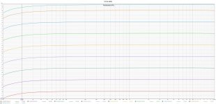
Some measurements with IRFP150 at Id 800mA done at 1/4 W to 44W output power.
SPL drops 0.6 dB at 20 Hz. I can live with that; easily fixed in the DSP.
THD at 20Hz listed at the bottom:
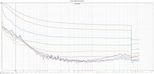
THD at 1kHz listed at the bottom:
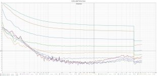
2HD at 1kHz listed at the bottom:
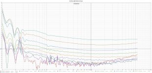
3HD at 1kHz listed at the bottom:
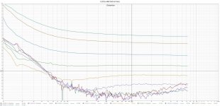
So THD is below -40dB (1%) at 20Hz. I reckon that the speaker distorts even more, so I can even use this as a sub speaker amplifier.
SPL drops 0.6 dB at 20 Hz. I can live with that; easily fixed in the DSP.

THD at 20Hz listed at the bottom:

THD at 1kHz listed at the bottom:

2HD at 1kHz listed at the bottom:

3HD at 1kHz listed at the bottom:

So THD is below -40dB (1%) at 20Hz. I reckon that the speaker distorts even more, so I can even use this as a sub speaker amplifier.
- Home
- Amplifiers
- Pass Labs
- Improving SLAPS - introducing X-SLAPS
