What's with the voltage source at the bottom of the schematic?
Simulation purposes? Some kind of bias, how can it then pass the input capacitors?
Anyway, I'll start to build this right away.
Thought I would separate the PSUs and SLAPS coils from the rest with a five part cable.
Just to see if the 3rd HD will be lowered; my suspicion is that for the lower part of the spectra, the hum and buzz from the SMPSs are the culprits.
It'll also be easier to for example place the SLAPS coils in different geometrical constellations. Why not anti-parallel?
I think it would be beneficial to have the two IRFPS3810 on the same heat sink.
After that I have verified this configuration, I'll start to play with introducing a very small amount of source resistors.
Perhaps I'll hit that sweet spot on the triode curve that you talked about.
solhaga and Circlomanen, thank you for suggesting a clean and elegant topology.
What about using a CFP (MOSFET-BJT) rather than single MOSFETs?
If more of the the power to drive the load can come from the slaved BJT rather than the MOSFET, wouldn't that give more freedom for choosing a MOSFET with improved characteristics? (lower capacitance, better transfer curve).
What about using a CFP (MOSFET-BJT) rather than single MOSFETs?
If more of the the power to drive the load can come from the slaved BJT rather than the MOSFET, wouldn't that give more freedom for choosing a MOSFET with improved characteristics? (lower capacitance, better transfer curve).
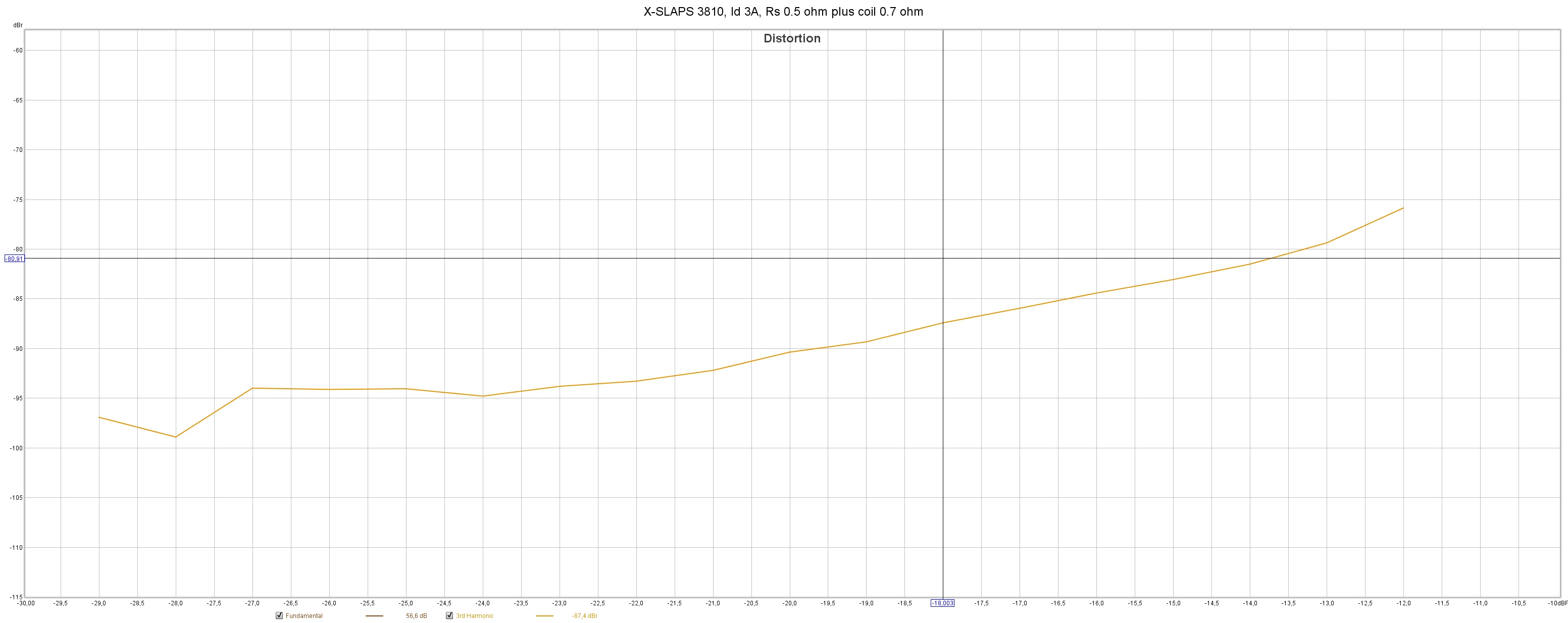
First measurements without the source resistors; it's only resistance in the coil, 0.7 ohm.
All measurements are at 1000 Hz and from an input level corresponding to 0.25 W (-29 dB) to 13 W (-12 dB) with 1 W at -23 dB.
The HDs got better with increasing Id, but I stopped at 3A.
Uds is then about 20 V, so the heat sink is at 60 degrees Celsius
3rd HD with (0.5 ohm plus coil):
and without (only coil) source resistors:
Not much difference.
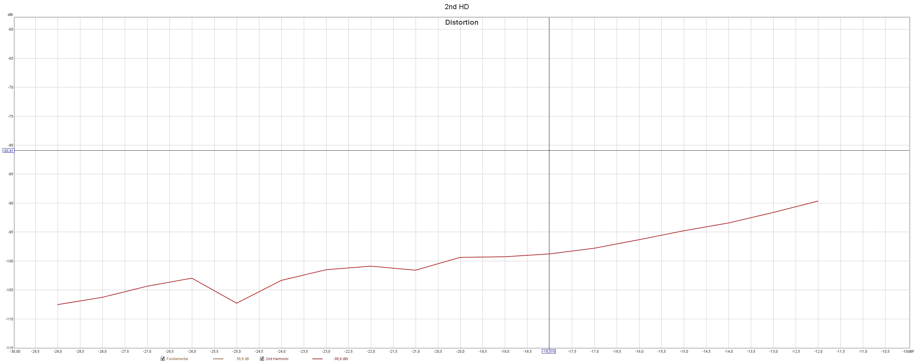
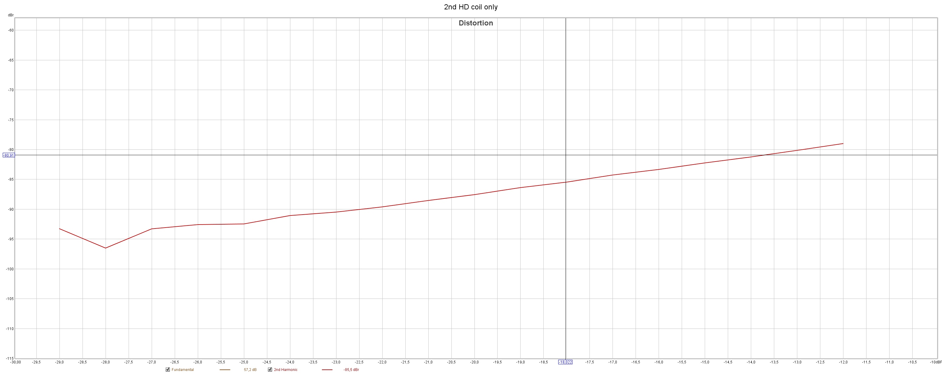
2nd HD with (0.5 ohm plus coil):
and without (only coil) source resistors:
So with the source resistors, the 2nd HD is actually about 15 dB better!
So, some source resistance is needed.
I'll start at 0.1 ohm.
All measurements are at 1000 Hz and from an input level corresponding to 0.25 W (-29 dB) to 13 W (-12 dB) with 1 W at -23 dB.
The HDs got better with increasing Id, but I stopped at 3A.
Uds is then about 20 V, so the heat sink is at 60 degrees Celsius
3rd HD with (0.5 ohm plus coil):
An externally hosted image should be here but it was not working when we last tested it.
and without (only coil) source resistors:
An externally hosted image should be here but it was not working when we last tested it.
Not much difference.
2nd HD with (0.5 ohm plus coil):
An externally hosted image should be here but it was not working when we last tested it.
and without (only coil) source resistors:
An externally hosted image should be here but it was not working when we last tested it.
So with the source resistors, the 2nd HD is actually about 15 dB better!
So, some source resistance is needed.
I'll start at 0.1 ohm.
Last edited:
If the second harmonic gets 15 dB worse without source resistors then this indicates a bad matching between the two sides - leading to less effective cancelation.
I would guess that the comparably much less reactive source resistors does a great job at linearizing the devices and making them much better matched over a much larger range of voltage and currents.
With very closely curve trace matched devices you would probably not need a lot of source resistance (local feedback) to get the lower second harmonic content.
Thanks for making all these measurements and experiments! Your feedback from real life amplifiers does provide me with lots of useful data! 🙂
If the second harmonic gets 15 dB worse without source resistors then this indicates a bad matching between the two sides - leading to less effective cancellation.
I would guess that the comparably much less reactive source resistors does a great job at linearizing the devices and making them much better matched over a much larger range of voltage and currents.
With very closely curve trace matched devices you would probably not need a lot of source resistance (local feedback) to get the lower second harmonic content.
Thanks for making all these measurements and experiments! Your feedback from real life amplifiers does provide me with lots of useful data! 🙂
I've tested today with 0.0, 0.1, 0.2, 0.3 ohm and 0.47 ohm as source resistors and both 2nd and 3rd HD gets better for every increase of Rs.
But not as good as the 0.5 measurement above that was done a couple of days ago.
I just remembered that when I started the measurements today, I accidentally broke off the drain pin of one of the MOSFETs and I had to replace the MOSFET.
So the 0.5 source resistor measurement above must have been done with more closely matched MOSFETs.
Comparing 0.5 to 0.47 ohm measurements shows that the better matched 0.5 measurement has 10 dB better 2nd HD.
Which proves your point!
I'd better do some curve tracing then or just keep changing one MOSFET.
I have already measured Ugs for all the MOSFETs but that was only done at one operating point with a
An externally hosted image should be here but it was not working when we last tested it.
.

I tested a CFB pair in a normal SLAPS, and it does work nicely. This is with simple stock devices and no real optimization.
It will need some high frequency compensation as it does show a peak and some phase issues at a few hundred kHz.
I have not made a full XSLAPS simulation yet, and personally I prefer a more simple single Mosfet setup over the CFB pair version.
Each SLAPS coil has two times 100 meter, so for an X-SLAPS configuration you need four times 100 meter.
The wire has an area of of 2.5 square mm.
Note that the coil has a 40 by 40 mm iron core comprising of eight 5 by 40 mm bars.
I don't know what Am+Bm is.
The wire has an area of of 2.5 square mm.
Note that the coil has a 40 by 40 mm iron core comprising of eight 5 by 40 mm bars.
I don't know what Am+Bm is.
Don't pay attention to A and B. It was meant for SLAPS bi (A+B)fill-ment. I work in automatization fabrique, but they refused to sell me the wire that is not usable according to latest specs. 400m for single channel adds up to quite expensive system. I don't think I can afford that at the moment. Yet I am interested in observing. Please keep on updating us. Very pleasant spectrum of physics this is.
The cheapest wire that I've found is SEK 496 retail price for 100 meters.
One core will cost you about SEK240.
So for SLAPS coils in an X-SLAPS, it's about SEK 1500.
Then the SMPSs about SEK 500.
Then there's the heat sink, the actual MOSFETs and the other electronics.
You must have a pre-amplifier with a gain of about 10.
This as the SLAPS and X-SLAPS have a gain of two.
For the X-SLAPS it must have differential outputs.
Last edited:
Sorry, some miscalculation. Here's the correct sums I hope:
The cheapest wire that I've found is SEK 496 retail price for 100 meters.
One core will cost you about SEK 240.
So for SLAPS coils in an X-SLAPS, it's about SEK 2500.
The SMPSs is about SEK 500.
Then there's the heat sink, the actual MOSFETs and the other electronics.
You must have a pre-amplifier with a gain of about 10.
This as the SLAPS and X-SLAPS have a gain of two.
For the X-SLAPS the pre-amplifier must have differential outputs.
All in all, for a stereo pair you should be able to get under SEK 8000.
But then of course you don't get any NFB.
Wire is cheaper here. I am just bad at saving. I used 180m of 0,2mm silver coated wire (somewhat 15ish ohm DCR) for my germanium amp (each channel). Still having it playing. But this one came from ship and for free. Still have some 600m of it. Your's work will be noted and maybe in future I'll pass by it again. Never know, what is gonna fall out of blue in your hands again.
I'd better do some curve tracing then or just keep changing one MOSFET.
I have already measured Ugs for all the MOSFETs but that was only done at one operating point with a .
So what's the best of doing this.
Adjust Ugs so that the two MOSFETs have the same Id or
have the two Ugs the same regardless of Id?
Matching IRFPS3810 proved to be tricky; still after 90 minutes the Vgs's and Id's haven't reach their final values.
IRFP044 on the other hand, proves to be stable .
Starting at Ids of 2010/2003 mA with Vgs 3.364/3.391 V, they increased to 2039/2024 mA with Vgs 3.333/3.365 V after 20 minutes.
I then did a re-calibration so that the Ids was 1993/1993 mA with Vgs 3,333/3,365 V.
Still after another 40 minutes (60 minutes total) Ids are 2000/2000 mA with 3.325/3.361 V.
I have also checked every 10 minute.
I have noted that Vgs differs about 30 mV for all instances.
So I'd would say that X-SLAPS with IRFP044 is possible to match after 20 minutes.
Here's how the IRFPS3810 and IRFP044 measures (still not matched other than low current Vgs matching) after 60 minutes, still no Rs.
IRFPS3810:
IRFP044:
So at 1 W (that's -23 dB input level) IRFPS3810 has 2nd/3rd HD -90.1/-93.6 dB and IRFP044 -96.6/-105.3 dB.
And at 13 W (that's -12 dB input level) IRFPS3810 has 2nd/3rd HD -80.2/-73.8 dB and IRFP044 -84.8/-86.5 dB.
So I'd say IRFP044 is a winner, it is matchable and will most probably have better HD levels (about 10 dB according to above).
Starting at Ids of 2010/2003 mA with Vgs 3.364/3.391 V, they increased to 2039/2024 mA with Vgs 3.333/3.365 V after 20 minutes.
I then did a re-calibration so that the Ids was 1993/1993 mA with Vgs 3,333/3,365 V.
Still after another 40 minutes (60 minutes total) Ids are 2000/2000 mA with 3.325/3.361 V.
I have also checked every 10 minute.
I have noted that Vgs differs about 30 mV for all instances.
So I'd would say that X-SLAPS with IRFP044 is possible to match after 20 minutes.
Here's how the IRFPS3810 and IRFP044 measures (still not matched other than low current Vgs matching) after 60 minutes, still no Rs.
IRFPS3810:
An externally hosted image should be here but it was not working when we last tested it.
IRFP044:
An externally hosted image should be here but it was not working when we last tested it.
So at 1 W (that's -23 dB input level) IRFPS3810 has 2nd/3rd HD -90.1/-93.6 dB and IRFP044 -96.6/-105.3 dB.
And at 13 W (that's -12 dB input level) IRFPS3810 has 2nd/3rd HD -80.2/-73.8 dB and IRFP044 -84.8/-86.5 dB.
So I'd say IRFP044 is a winner, it is matchable and will most probably have better HD levels (about 10 dB according to above).
This is how far I got with IRFP044, I'm sure that better matching can be done though:
2nd HD went down 6 dB and more, THD 4 dB or so.
I'd say that it is pretty impressive of a two MOSFET 13 W amplifier with no NFB.
I will now continue with the 44 W X-SLAPS (SLAPS for bass) that consists of IRFP150 MOSFETs.
An externally hosted image should be here but it was not working when we last tested it.
2nd HD went down 6 dB and more, THD 4 dB or so.
I'd say that it is pretty impressive of a two MOSFET 13 W amplifier with no NFB.
I will now continue with the 44 W X-SLAPS (SLAPS for bass) that consists of IRFP150 MOSFETs.
2nd HD went down 6 dB and more, THD 4 dB or so.
I'd say that it is pretty impressive of a two MOSFET 13 W amplifier with no NFB.
Warning! My post may contain subjective rant about sonic character of amplifiers!
In my experience there is a very different sonic character to feed forward error correction which is based on positive feedback, compared to the more normal local and/or global negative feedback.
Due to the positive feedback used to force the output to adhere to the input signal, feed forward error correction tends to sound very powerful and "alive" with a very organic effortless presence - often to a surprising degree considering the low output power in this kind of amp.
13 watts might not normally be considered powerful, but my prediction is that this XSLAPS will sound even more effortless with abundant power and dynamic vitality then the normal SLAPS.
In my experience from several variations with the SLAPS design and with some experimentation with several different Mosfets, I find these amps very smooth "liquid" and free from any "electric grain" or other unnatural character I often find prevalent in normal big number power amps that relay on generous amounts of negative feedback for their published specs.
This XSLAPS should combine the balanced cancelation of even order harmonics with some real control over the cone and some quite heavy handed dynamic capabilities (when called for). This is without sacrificing the sweet smooth and effortless presence the SLAPS excels at.
When the mechanism used to flatten the transfer curves and lower distortion is based on very electrically "robust" bifilar coils and lots of quiescent current running through the Fets, then nothing a highly reactive load (loudspeaker and crossovers) can do will disturb the amp while it is doing its thing!
- End of subjective rant.
I will now continue with the 44 W X-SLAPS (SLAPS for bass) that consists of IRFP150 MOSFETs.
😱🙂


This is the closest non-inductor version of a SLAPS I can come up with.
It is a simple version of the Tringlotron. It can have so much positive feedback in the feed forward error correction that it gets a negative output impedance.
Something similar to this design but with Nelson Pass SITs could be a lot of fun. 🙂
It does have its drawbacks though. The available output voltage swing is very poor compared to the inductor loaded version. It is prone to high frequency instability (it is very very fast already with normal Mosfets) and it needs close matched pairs of devices closely mounted on a heat sinks for close thermal tracking. Lots of heat for comparably less output power then the SLAPS or XSLAPS.
Several complex versions of the Tringlotron has been explored in the Solid State section of this forum and TubeCad has covered the Tringlotron several times. But I have never seen it in the Pass section, even though it is novel way to incorporate true feed forward error correction (not a cleverly hidden negative feedback) in a reasonably simple design with a few mosfets, SITS or SIC Jfets, lots of heat and a beefy powersupplies (all hallmarks of Pass designs, which is why I post this here).
View attachment 904808
View attachment 904809
This is the closest non-inductor version of a SLAPS I can come up with.
It is a simple version of the Tringlotron. It can have so much positive feedback in the feed forward error correction that it gets a negative output impedance.
Something similar to this design but with Nelson Pass SITs could be a lot of fun. 🙂
It does have its drawbacks though. The available output voltage swing is very poor compared to the inductor loaded version. It is prone to high frequency instability (it is very very fast already with normal Mosfets) and it needs close matched pairs of devices closely mounted on a heat sinks for close thermal tracking. Lots of heat for comparably less output power then the SLAPS or XSLAPS.
Several complex versions of the Tringlotron has been explored in the Solid State section of this forum and TubeCad has covered the Tringlotron several times. But I have never seen it in the Pass section, even though it is novel way to incorporate true feed forward error correction (not a cleverly hidden negative feedback) in a reasonably simple design with a few mosfets, SITS or SIC Jfets, lots of heat and a beefy powersupplies (all hallmarks of Pass designs, which is why I post this here).
I've put it in my backlog.
I've put it in my backlog.
I've just pulled this from the backlog though: X-SLAPS 44 W with IRFP150:
An externally hosted image should be here but it was not working when we last tested it.
Due to the higher supply voltages, I do need to have three parallel MOSFETs a side.
- Home
- Amplifiers
- Pass Labs
- Improving SLAPS - introducing X-SLAPS