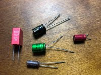
But for coupling caps, I don't know, I don't trust those smallish caps and prefer NP/BP. In my ears, some vintage NP/BP is equal or better sounding than Black Gate N.
Actually these mks2 caps are not so small , 10uf/50v plastic is going to be at least same size if not larger than an 10uf/50v electrolytic.
I cant say I compared mks2 with other polyester caps, it's just that mks2 has 5mm lead spacing and is available at mouser/digikey. 600v coupling caps will be way too large and more expensive. I would be very happy just with mks2/ MKT370/mkt470 or other ones or even np electrolytics like nichicon es.
I think these are the candidates for coupling caps where space is limited.
Attachments
Last edited:
BTW,
The maximum capacitance for such a smallish cap will be 2u2. You can increase the capacitance from 1uF to 2.2uF with better result. But not the one in the crossover as that will affect the frequency.
I funded Coupling Capacitor Calculator
My has 50Kohm input best for 0Db on 20hz 1.6uf .
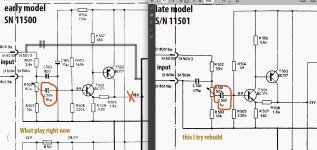
Other strange things amplifier the same on early and late models Braun but different crossover and preamps for crossover with the same frequency cut . Also different coupling caps on old 10uf on newer model 1uf . I play music on old model right now .
On my old model one time I bypass preamp for crossover like I show on schematic and sound much more fat, less compress like 2 times , more real then with preamp . For example if play one speaker stereo sound not full like two speakers together side by side , then I bypass preamp one speaker start sounding real like two speakers together .
May be not so good preamp ? I use DAC with 50ohm output
Attachments
If it’s a coupling cap you can use a larger value , instead of 1u u could use 2.2, 3.3 or even 10uf. It is not the best , some will say that the amp will be more sensitive to noise, radio or cell phones....
If it’s a coupling cap you can use a larger value , instead of 1u u could use 2.2, 3.3 or even 10uf. It is not the best , some will say that the amp will be more sensitive to noise, radio or cell phones....
I try without input coupling caps play music , any shifting on, off electrical devices in home make big pulse from speakers .
I read people add bypass capacitor like :
Better caps of smaller values can be used in parallel with bigger ones (like a 22uf electrolytic with a 100nf polypropylene) to significantly improve performance (a practise called bypassing).
Other post : Vishay MKT1822 MKT 63VDC - 1% tolerance
Sound: Well balanced, overall coherent sounding capacitor. It doesn't have as much depth as the more high-end type capacitors and micro-detailing is limited but somehow it did stay in the back of my head as nice and pleasent to listen to. You can boost the overall presentation a lot by adding 0,01uF's worth of MKP1837 parallel. So if you are looking for a cost effective and very compact alternative to MKP capacitors like the Solen Fast Cap, look no further!
If interesting this just like info : Capacitor Test look like test was on passive crossover.
Yes. The real deal is not the 20Hz frequency, not the 0dB at 20Hz, not even phase at 20Hz. But yes, this is about phase.I funded Coupling Capacitor Calculator
My has 50Kohm input best for 0Db on 20hz 1.6uf .
Bigger than 1uF should be better, as long as the capacitor type is the same. The author mentioned that more isn't always better, choose the smallest that will give you the right -3dB. He gave example with output cap, which quite different with your situation.
With output cap, the capacitance is bigger and it is electrolytics type. The bigger the capacitance, the worse the quality (higher dissipation factor, higher current leakage, I think inductance too). So that's right, keep it minimum.
With smaller cap and especially metallized caps, situation could be different. I have never noticed or experienced a drop in quality caused by increase from 1uF to 22uF of the same NP type.
And who cares about how many dB down at 20Hz. Nobody can hear that.
Any circuit will add noise and distortion. That's why some people prefer to choose a circuit that doesn't require coupling cap, as the coupling cap will ruin the sound. But the coupling cap is needed in the circuit to avoid DC.I bypass preamp for crossover like I show on schematic and sound much more fat, less compress like 2 times , more real then with preamp . <snip>
May be not so good preamp ? I use DAC with 50ohm output
If you are thinking about better circuit, in general most people I think will agree that JFET circuit will sound better.
No doubt that you will hear more transparancy with shorter circuit, but transparency is not the only thing you should consider. But if you really think that without a buffer, you hear improvement, then its your call. I found it strange tho...
Yes, your DAC might have good capability to drive low impedance. But some people even put buffer at each crossover path (high, mid, bass). I use only one buffer for all paths (like in your Braun). I don't know how it will sound without it. Think (or listen) again.
Hi Pashka,
Use a film capacitor. 2u2 to 4u7 will be more than large enough.
You can't parallel a larger capacitor with a small one to improve response. The biggest problem is DA in the capacitor. That energy is lost no matter what you stick in parallel. So just use a good film capacitor. Even 1u0 is large enough, but you can get larger capacitors with a 5mm lead spacing. May as well go that route. I didn't suggest higher than 4u7 because the prices rise very quickly with capacitance. Decent capacitors will have voltage ratings of 50 to 63 VDC.
-Chris
Thanks anatech Can I make longer leg of capacitor and install big one , can be any problem ?
Thanks everybody > My last post was deleted by mistake . Still read a lot of information , study step by step . First so I want to do make a life second set Braun recap change same bad transistors and see how is sounding different crossover schematic . Also need recap my actual set amps Braun , compare sounding different capacitors and add bigger like 10Kuf or 15Kuf TDK B41550 or B41560 for PS capacitor for MF, LF amps without new transformer , for now . Is 15000uf w'll be OK or start with 10000uf ? But I things extra power like separate ( transformer, bridge, capacitor ) possible w'll make difference . Also I have Oscilloscope , my new toy.
On board looking very bad trimming resistors , for adjusting level crossover 2.5Kohm and bias 250ohms . Which one you can recommend for Bias trimmer 250ohm ?
Hi Pashka,
Yes. Capacitors that are too large will cause problems. If a part doesn't fit, you can't use it. The film capacitors can have their leads bent to a smaller spacing, but they are not heavy enough to damage the traces or pads.
Do not increase the supply capacitance much beyond what the amplifier has in it right now. You can go from 12K to 15K or thereabouts without too much trouble. But increasing the capacitance past that is asking for trouble. There is no way I would use an 18K or higher for example. Trouble? Inrush current and very short diode conduction angles. Nothing there is beneficial for you.
-Chris
If you are thinking about better circuit, in general most people I think will agree that JFET circuit will sound better.
Yes, your DAC might have good capability to drive low impedance. But some people even put buffer at each crossover path (high, mid, bass). I use only one buffer for all paths (like in your Braun). I don't know how it will sound without it. Think (or listen) again.
I think your last post is the same accidentally deleted.. Very interesting make something like on JFET boost . I was thinking maybe bring balance signal to amp and unbalance with new buffer ?
Hopefully I'll get down to working on the amplifier soon , just waiting same parts and I let you know what different between without and with buffer preamp on braun, It will be great if I can see it through an oscilloscope , all harmonics and distortion .
Thanks Chris .Hi Pashka,
Yes. Capacitors that are too large will cause problems. If a part doesn't fit, you can't use it. The film capacitors can have their leads bent to a smaller spacing, but they are not heavy enough to damage the traces or pads.
Do not increase the supply capacitance much beyond what the amplifier has in it right now. You can go from 12K to 15K or thereabouts without too much trouble. But increasing the capacitance past that is asking for trouble. There is no way I would use an 18K or higher for example. Trouble? Inrush current and very short diode conduction angles. Nothing there is beneficial for you.
-Chris
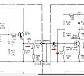
So on schematic 5000UF capacitor for LF and MF amps .
Bridge B80C5000 , may be get new one w'll be better ?
Sounds like maybe some of the Wima mks2 would work for coupling perhaps?
The 4.7uf version has 5mm spacing on the leads, is fairly small.
The 4.7uf version has 5mm spacing on the leads, is fairly small.
Yes , thanks phase , about MKS2 tell me asuslover Two times in the same place is not casual.Sounds like maybe some of the Wima mks2 would work for coupling perhaps?
The 4.7uf version has 5mm spacing on the leads, is fairly small.
Interesting information from WIMA :
https://www.wima.de/wp-content/uploads/media/WIMA-Audio.pdf
Maybe I missed something, sorry. Is it possible to put one coupling capacitor in instead of two between the crossover and the amplifier?
Attachments
I did see that they aren’t recommending that type for signal coupling, however, the specifications suggest that it should be better than an electrolytic part in that position.
Sorry I hadn’t read the entire thread so far.
Another thing I always do when upgrading audio equipment is to use a X specified capacitor across the incoming AC power. A .1uf usually works just fine to help clean up the line.
After that I try and apply a snubber directly on the diode bridge to help quiet the switching noise from that. I have used a .01uf across the AC side of the diode bridge, or across the transformer out leads, however you want to look at it. In addition to that, another .1uf in series with a 15 - 20 ohm resistor, across the same. I use a 3watt resistor and Russian k71-4 polystyrene capacitors.
These are some fairly inexpensive upgrades that have yet to make anything sound worse to say the least. A lot of listening will make whatever you do more appreciated, and that takes time. Lots of time.
Hi Pashka,
I would leave both capacitors in circuit. Some other products don't have coupling capacitors. Their designers should be shot (several times).
Those film capacitors are fine for signal coupling. I've used them often and have tested them on my HP LCR meter. They are a lot better than an electrolytic capacitor.
-Chris
 Thanks Chris . Got it . I put two film capacitors as indicated by the scheme.
I did see that they aren’t recommending that type for signal coupling, however, the specifications suggest that it should be better than an electrolytic part in that position.
Sorry I hadn’t read the entire thread so far.
Thanks phase
The whole branch is not interesting as I try to get into and improve sound on Braun LV 1020 without knowledge . Everything in my head a mess, a lot of new things, I try to sort it all out in my head. All new to me, gnawing science. But I will make a super sound on these unique active speakers, though not soon. Step by step .
fyi, i used a 1ufd/63volt film cap in an input cap that called for 10ufd/25volt ecap....bass was tight and fast...
It possible then speakers not play lower 50hz . A lot of like this .
1uf cut low frequency , working like low cut filter , for many speakers this is good ,don't need play what can't play.
1uf cut low frequency , working like low cut filter , for many speakers this is good ,don't need play what can't play.
^or what is not in the program material in the first place...
years ago, i read that big coupling caps are good in the noise department, the same book never mentioned about bass response being better with bigger coupling caps...
years ago, i read that big coupling caps are good in the noise department, the same book never mentioned about bass response being better with bigger coupling caps...
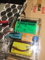
Finally today arrive original 2N3055 transistors from Germany old / new stock for my second set amplifiers. I want get match pair transistors but I dot- know what need match . It is possible match this transistor with tester what on picture (I don't know name) .??? How right match transistors ? What important hFE or Uf ? How close must be digit between transistors ? Thanks .
I got 100 x2N3055 original , If somebody need ones let me know .
I got 100 x2N3055 original , If somebody need ones let me know .
Attachments
Last edited:
Hi Pashka,
You need to match beta. Uf differences will be swamped by the tolerance of emitter resistors.
Because transistor parameters are extremely temperature dependent, the transistors must be at the same temperature as you measure them. That means allow them hours to equalize and then measure them without touching them in any way. Don't even breathe on them as that will throw out the readings. Why not set them up now and measure them tomorrow morning first thing?
-Chris
Thanks Chris . I TRY UNDESTEND, what need match . I have chinise box , it show transistor and Uf and hFE . Yes I try test and heat transistor in my hand and parameters was change . Chris I reading right now this one , I just search with two uniq words "match beta" . A lot of new stuff for me , before I grow up i need know what parameters need match Uf or hFE or together and how perfect between transistors ? Thanks
- Status
- Not open for further replies.
- Home
- Amplifiers
- Solid State
- Improving Braun LV1020