Isn’t it like food Anetech everyones got different taste buds. You may be able to pic the best caps with your Lcr meter but that does not mean that it will sound gd to another persons ears. If the circuit is design from ground up, what you say holds true to a certain extend & even if it is very very well design it does not mean that one cannot improve sound further by careful selection & placement of passive components.
Hi sumotan,
In long experience, the lower distortion results were always prefered by customers. I guess if the equipment you are working on isn't very good, then adding a flavour to the sound quality might be an amusing distraction. But in no way is that good audio at all.
Case in point. I just rebuilt a Marantz 7 (a real one). Starting out the distortion measured over 1% at 2 volts out. After the rebuild replacing both resistors and capacitors, the distortion measured 0.0055%. A massive improvement. The customer called tonight actually, and he was annoyed that music from crappy sources sounded worse, but when pressed he admitted that good music sources and masters sounded a lot better. So when I asked him what he wanted done, he said he'll try to make up his mind. Previously the preamp hid all the defects because it really manged the sound going through it hiding the poor quality. However with the highs restored , the older music (1950's through mid 70's) couldn't hide behind equipment any more.
So, the rebuilt preamplifier now shows the truth instead of glossing over the bad bits. He listens to good quality music normally. I'm pretty confident he will choose the cleaner version of that preamp.
So you see, introducing distortion and noise might satisfy someone short term, or until they hear something really good compared to their current stuff. But reducing distortion and noise floor is always the right direction. The better capacitors do not have a sound (or minimal at best).
One further comment folks. Capacitor ESR is not the parameter that matters in the audio path. It is entirely pointless to make decisions on ESR except in maybe filter capacitors. What the most important thing to look for is called dielectric absorption. What that is is energy lost in the dielectric of the capacitor (= distortion, or having a voice for example). Unfortunately, good meters that do an accurate job of measuring dielectric absorption (or DA) are more expensive than the cheap meters that measure series resistance. So there is a cost to admission to that party. But wouldn't you rather be right than being hit and miss by chance?
Also, if someone is charging me to work on my equipment, I expect them to have the proper instruments to support what they are charging me for. Guesswork doesn't cut it these days. The better the equipment sounds, the more people will make the choice to listen to it. When you are dealing with cheap, "junky" electronics (example NAD 3020), all bets are off. But it would seem to be intelligent to take the path of improved performance (lower distortion and noise) than trying to colour the sound, maybe to hide the problems?
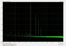
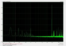
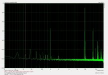
Here is the tests for the right channel of that preamp I was talking about. Tell me which one you would rather hear your music through!
Well, over 30 years experience and my customers would strongly disagree with you and the voodoo you seem to be pushing.Isn’t it like food Anetech everyones got different taste buds.
In long experience, the lower distortion results were always prefered by customers. I guess if the equipment you are working on isn't very good, then adding a flavour to the sound quality might be an amusing distraction. But in no way is that good audio at all.
Case in point. I just rebuilt a Marantz 7 (a real one). Starting out the distortion measured over 1% at 2 volts out. After the rebuild replacing both resistors and capacitors, the distortion measured 0.0055%. A massive improvement. The customer called tonight actually, and he was annoyed that music from crappy sources sounded worse, but when pressed he admitted that good music sources and masters sounded a lot better. So when I asked him what he wanted done, he said he'll try to make up his mind. Previously the preamp hid all the defects because it really manged the sound going through it hiding the poor quality. However with the highs restored , the older music (1950's through mid 70's) couldn't hide behind equipment any more.
So, the rebuilt preamplifier now shows the truth instead of glossing over the bad bits. He listens to good quality music normally. I'm pretty confident he will choose the cleaner version of that preamp.
So you see, introducing distortion and noise might satisfy someone short term, or until they hear something really good compared to their current stuff. But reducing distortion and noise floor is always the right direction. The better capacitors do not have a sound (or minimal at best).
One further comment folks. Capacitor ESR is not the parameter that matters in the audio path. It is entirely pointless to make decisions on ESR except in maybe filter capacitors. What the most important thing to look for is called dielectric absorption. What that is is energy lost in the dielectric of the capacitor (= distortion, or having a voice for example). Unfortunately, good meters that do an accurate job of measuring dielectric absorption (or DA) are more expensive than the cheap meters that measure series resistance. So there is a cost to admission to that party. But wouldn't you rather be right than being hit and miss by chance?
Also, if someone is charging me to work on my equipment, I expect them to have the proper instruments to support what they are charging me for. Guesswork doesn't cut it these days. The better the equipment sounds, the more people will make the choice to listen to it. When you are dealing with cheap, "junky" electronics (example NAD 3020), all bets are off. But it would seem to be intelligent to take the path of improved performance (lower distortion and noise) than trying to colour the sound, maybe to hide the problems?
Here is the tests for the right channel of that preamp I was talking about. Tell me which one you would rather hear your music through!
Attachments
Hey Anatech
I thought you mention to keep an open mind. I don’t practice or try to push Voodoo ya
Im just sharing my findings & I don’t charge anyone for my services. So pls let’s not argue due to difference of opinion. It’s just too bad that we’re too far apart for not I’ll invite you over to have a listen on my set up & you be the judge.
Cheers
Hi sumotan,
Human beings are not test instruments and are not calibrated at all. Our references drift, so you can't trust your opinion on how something sounds (within reason). With informed training assisted with test equipment you can settle in on a reference that you can compare to. Humans are reasonably good at comparing things, but they still need some training to recognise accurate sound reproduction. A really good reference system really helps as well. You will find that really good sounding systems also measure well. When the quality isn't high, you can get away with murder!
Everyone here is trying to put in the best effort they can. So pointing people in the right direction is important. Charging for your opinion or not isn't important here. What is important is to be correct, because there are hundreds of people who will read what is offered up as information. Most people reading this never post, but "you" have na effect on them just the same. "you" means everyone who posts in any thread. Isn't that a sobering thought?
Many service people read what is on the internet and simply implement what they read and pass that off as their knowledge. I've seen several pieces of equipment serviced exactly as some article or report spells out. People are being charged for the information given from every corner of the internet. Paint by numbers with no understanding of what they are doing. At least help them get it right.
-Chris
I completely agree with keeping an open mind - except when there is overwhelming proof that shows something is true. Can you imagine science, or even a court of law if they ignored certain proof and entertained any and all theories? What a mess! When there is proof, and instead of providing just my word, I attached proof as well.I thought you mention to keep an open mind.
Human beings are not test instruments and are not calibrated at all. Our references drift, so you can't trust your opinion on how something sounds (within reason). With informed training assisted with test equipment you can settle in on a reference that you can compare to. Humans are reasonably good at comparing things, but they still need some training to recognise accurate sound reproduction. A really good reference system really helps as well. You will find that really good sounding systems also measure well. When the quality isn't high, you can get away with murder!
Everyone here is trying to put in the best effort they can. So pointing people in the right direction is important. Charging for your opinion or not isn't important here. What is important is to be correct, because there are hundreds of people who will read what is offered up as information. Most people reading this never post, but "you" have na effect on them just the same. "you" means everyone who posts in any thread. Isn't that a sobering thought?
Many service people read what is on the internet and simply implement what they read and pass that off as their knowledge. I've seen several pieces of equipment serviced exactly as some article or report spells out. People are being charged for the information given from every corner of the internet. Paint by numbers with no understanding of what they are doing. At least help them get it right.
-Chris
May be the one on the left? On the left the distortion is very high but low order. On the right the distortion is much lower. I'm not saying that I like low order harmonics, I prefer lower distortion, but the two charts cannot tell the quality of the amp. Often, the lower distortion one sounds wrong, not because it is low distortion but because the designer tried too hard to lower the distortion, thinking that it is all that matter.Here is the tests for the right channel of that preamp I was talking about. Tell me which one you would rather hear your music through!
I had a Marantz 7. With the original design, at least it is euphonic. With whatever modification, I have no idea why the amp could sound good? 😀
Hi John,
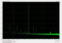
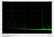
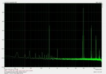
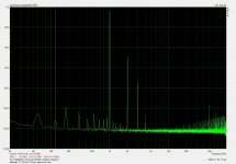
Sure, here is the left channel. I have IMD as well, they tell a similar story.
The rebuild included new tubes (Electroharmonix 12AX7EH) and replacement of the resistors and capacitors. The selenium rectifiers were replaced with silicon types. The main filter capacitors were surprisingly in good condition. I check the waveform across them under load with an oscilloscope. No leading edge "pips".
There was no change in schematic. It's a classic preamplifier that was well designed. I'm not going to second guess those excellent engineers. Therefore, if the same work was done to your 7, it would turn out the same way. It sounds much better now, but not as euphonic. That character is due to the carbon composition resistors. Terrible things.
I used to repair equipment with carbon composition because that was all that was available. 5% was considered high precision. 2% was just silly and we didn't ever see 1% resistors. We used to match resistors by cutting a notch into the side of the low value one and cut until the resistances were equal. Then seal it with a lacquer. Pretty barbaric, but that was what we were taught.
Attachments

Hi John,
Any good designer knows you can only optimize one trait at the expense of others in the design phase. When I design something audio, I listen and measure. Things have to pass both tests and good designs generally converge together. I have never met a good designer who doesn't listen to their work , and measure it.
It's a myth that designers design only with measurements. Actually, the reverse is more common where you have someone with some knowledge that "designs by ear". They typically don't have test equipment, or it's really old and next to useless. My own experience has shown that products designed by ear typically don't sound as good as they could, and have redesigned many pieces where the sound quality and performance was greatly enhanced. A good example of this would be Counterpoint equipment.
-Chris
Well Anatech the way that you’ve put it is like Im misguiding Pashka.
If you read again I actually advice him to just change the internal speaker wires to test.
We all have different opinions or methods to achieve objectives. Me Im just sharing what I’ve learn & discovered. Like most of us here, it’s up to the individual to test, learn & judge from their findings as well. We should leave our differences in opinion as is. The beauty of diy in itself is a journey of discovery be it done technically correct or not , success or failure one still learns from it.
Hi Chris,The rebuild included new tubes (Electroharmonix 12AX7EH) and replacement of the resistors and capacitors. The selenium rectifiers were replaced with silicon types. The main filter capacitors were surprisingly in good condition. I check the waveform across them under load with an oscilloscope. No leading edge "pips".
There was no change in schematic. It's a classic preamplifier that was well designed. I'm not going to second guess those excellent engineers. Therefore, if the same work was done to your 7, it would turn out the same way. It sounds much better now, but not as euphonic. That character is due to the carbon composition resistors. Terrible things.
Mine was using GE tubes. Resistors are carbon but the old Riken (gold plated one). I still have the complete module (along with the R-core transformer) but I have a prejudice of what it possibly can deliver, so I'm not motivated, or may be when I have to sell the stuff (no schematic modif, you said?). Apple to an apple (and low distortion too), how do you compare it with the octal Aikido? I have a feeling that you're not a tube guy so I think it is not up to your standard. May be you are an opamp guy? I have some AD797BRZ which should be able to deliver better measurement than any 12AX7!
Why would a 20000uF power supply capacitor kill the sound when it's used just for the LF stage? It certainly will not.
But now I had another look at your schematic, and it's a single supply design, with an electrolytic capacitor at the output. Is that the one you want to change to 22000uF?
It's different then.
Another thing it's using separate transformers and supplies for HF-MF-LF. Are the transformers voltages different?
I completely agree with Anatech on his comments.
To start with you have to have extremely good speakers to spot differences when you change such things as internal/external cabling, as long as all are good quality.
It's also true that sometimes you can't measure things you repeatedly hear. But that happens less and less nowadays. Good instruments are very expensive too.
If you really want to play with things, first of all you should train your ear and your listening. I have been a professional location and studio film/TV recordist for many many years, and I did have to train my ear. This is very important, and ANYONE can do. Focusing is the key to this.
You need to find non-electronic music, usually classical and with few instruments. Then you can focus and identify each instrument, paying attention to how it separates or integrates with the other instruments. Do that with every instrument, and then to the whole.
With time you will forget about that, but your ear will separate things automatically.
With parts changes, the key thing is not to "expect" a change. This is a very common mistake, IMHO, simple as it seems. Because then your mind may "imagine" there is a change. This is probably the hardest thing to do. But anyone can do it.
This is just an advice, not a teaching.
CALMART Thanks for help .
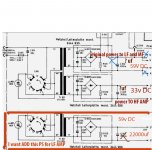
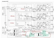
Yes I want add independent power for LF amp and change 5000uf to 22000uf capacitor (new transformer 200VA)
Original transformer got 2 output :
1. 59VDC to LF and MF amps.
2 Second one 33v to HF .
So what I know from internet 🙂 for LF amp is good large capacitor like 22000uf . For HF amp better keep like on schematic 3000uf.
What can you say what capacitance capacitors to put on each amplifier will be correct?
What bridges will apply to each amplifier?
Can there be any other ideas on how to do it right and better ??? . thankс
🙂
Attachments
May be the one on the left? On the left the distortion is very high but low order. On the right the distortion is much lower. I'm not saying that I like low order harmonics, I prefer lower distortion, but the two charts cannot tell the quality of the amp. Often, the lower distortion one sounds wrong, not because it is low distortion but because the designer tried too hard to lower the distortion, thinking that it is all that matter.
I had a Marantz 7. With the original design, at least it is euphonic. With whatever modification, I have no idea why the amp could sound good? 😀
at the time of the design, the 12ax7 was very much in season and designers wanted to build with those tubes...
but the 12ax7 had may too much gain for a line stage, so what to do then? use global negative feedback of course...
notice that the Marantz 7 line stage has a striking resemblance with that of the SP3...this topology is still being used in modern day line amps...i have seen line amps coming out of Hong Kong and china that are Marantz 7 clones....
today comes Broskie, his line stages using the lower mu triodes like the 12au7 can be made without needing for global negative feedback,just local feedback and gains of 20db are practical...
there are a lot of anecdotes posted here....
i have no problem with anecdotes,
after all they are the result of personal experiences....
and those never really swayed me....
if they sway another, then that is not my problem anymore...
but the science behind all of them are never subject to interpretations...but applications, practical or not is up to the individual...
yes, DIY'ers are endowed with inherent rights to get as crazy as they wish
so long as no components are hurt nor burned out in the process.... 😀
CALMART Thanks for help .
Yes I want add independent power for LF amp and change 5000uf to 22000uf capacitor (new transformer 200VA)
Original transformer got 2 output :
1. 59VDC to LF and MF amps.
2 Second one 33v to HF .
So what I know from internet 🙂 for LF amp is good large capacitor like 22000uf . For HF amp better keep like on schematic 3000uf.
What can you say what capacitance capacitors to put on each amplifier will be correct?
What bridges will apply to each amplifier?
Can there be any other ideas on how to do it right and better ??? . thankс
🙂
the choice of psu capacitance is very much dependent on amplifier topology and how well their power supply ripple rejection ratio is...how well do you know your circuit? or you are just taking the anecdotes as to how adding psu caps improve things? then it is a hit and miss thing...
ripple voltage is directly proportional to load currents and inversely proportional to capacitance in the psu....
if you know your full load currents and know your tolerable ripple voltage, then you can determine the size of your psu caps..
in the 1980 Walter Jung wrote an article about PSU energy bank in the AUDIO magazine, i asked permission to repost that article here, but i got denied, the author has since then had a change of heart...
you can of course do as you wish, after all it is your amp.....
If I say the phrase :
"ripple voltage is directly proportional to load currents and inversely proportional to capacitance in the psu ..." after these words, any girl would be willing to spend time with me. 🙂True, I will not do this, I am not at that age, although I have a young soul.
I looked and I know the circuit of the amplifier, but no more, just looked and then my knowledge ends there. What can you say and advise for improvement. Amplifier circuit 70 years. I can hold a soldering iron in my hands. I really like the sound of everything that I had and I would like to squeeze the maximum.
This is amplifiers schematic . Thanks in advance for your help .
Attachments
one thing i am not fond of doing.....messing up with a working amp...but hey it is just me....😀
and i am also not keen on telling people what and how to do their thing...i can give pointers and the work is really up to them...
i throw stones in the air, catch them if you will....
and i am also not keen on telling people what and how to do their thing...i can give pointers and the work is really up to them...
i throw stones in the air, catch them if you will....
Hi John,
If anything, I am comfortable with tube, transistor and IC technology. I even have surface mount equipment and repair that stuff. I have been the service manager for advanced products like Cyrus, and most high end products. I owned a high end audio service company for 16 years before I sold it. We also did recording studio service.
So, no. I'm not any kind of guy that can be pigeonholed into those headings.
Each technology has its attributes. My main amplifier is a Marantz 300DC that I've improved, then we'll put my Eico HF-87 (improved) into the same system and listen to that. I admit that I don't have any chip or class "D" amplifiers. I don't think they are ready yet. The speakers are PSB Stratus Gold (original), which the tube amps drive without any problems. The tube amps are rated for 35 and 40 watts per channel. Many stereotypes broken in this house. There are also other systems here and there that include Luxman, Carver. Mostly Marantz. Stereos tend to accumulate in my business.
As for what technology should be used, just the best component for the job. So for power supply regulation, you're better off with solid state. I do have tube regulators as well, even for test equipment.
Here's a money shot of the prototype amplifier.
-Chris
It works better than an Aikido I recently had to help with grounding and signal cable paths. It was okay, but the Marantz enjoys a better overall design. Also, feedback is not an evil thing as long as the circuit is designed well to begin with. Given the performance you can see in those reports I posted, it performs well with anything new.... how do you compare it with the octal Aikido?
I learned on transistors in school, but learned tubes first in my occupations. I just designed a tube power amp as a commercial product. I'm almost done, and it worked first time it received full power. 🙂 Love that. It is mostly point to point wiring with PCB circuitry for the power supply regulators. My hobby for years was repairing radios from the 20's up into the 50's, and audio equipment right up to present.I have a feeling that you're not a tube guy so I think it is not up to your standard.
If anything, I am comfortable with tube, transistor and IC technology. I even have surface mount equipment and repair that stuff. I have been the service manager for advanced products like Cyrus, and most high end products. I owned a high end audio service company for 16 years before I sold it. We also did recording studio service.
So, no. I'm not any kind of guy that can be pigeonholed into those headings.
Gee, I have some too, and the LME49xxx series, and eve some cutting edge OPAxxxx ICs. I've designed lots of solid state and IC based products too.May be you are an opamp guy? I have some AD797BRZ which should be able to deliver better measurement than any 12AX7!
Each technology has its attributes. My main amplifier is a Marantz 300DC that I've improved, then we'll put my Eico HF-87 (improved) into the same system and listen to that. I admit that I don't have any chip or class "D" amplifiers. I don't think they are ready yet. The speakers are PSB Stratus Gold (original), which the tube amps drive without any problems. The tube amps are rated for 35 and 40 watts per channel. Many stereotypes broken in this house. There are also other systems here and there that include Luxman, Carver. Mostly Marantz. Stereos tend to accumulate in my business.
As for what technology should be used, just the best component for the job. So for power supply regulation, you're better off with solid state. I do have tube regulators as well, even for test equipment.
Here's a money shot of the prototype amplifier.
-Chris
Attachments
Hi Chris, thanks for the info.
I have DIYed a speaker based on the Stratus Gold, with Vifa D25AG, P17WJ, PL26. Now I'm using similar but smaller, more exotic drivers and active!
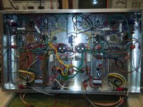
#1. The drivers. The tweeter and dome midrange look good.
#2. Simple active crossover designed for the chosen drivers.
I have saved the circuit (thanks) so I can make similar design for different drivers. The transistors are not the best, but you cannot just put different transistors without changing the design. Parts values should be precise in a crossover filter.
Resistors on the filter circuit could be noisy. Changing to Dale RN60D may improve things if not too expensive.
Power supply can be more regulated using Capacitance Multiplier. This should give huge effect I believe.
The orange capacitors on the filter seems to be Siemens which sound good. The yellow axial one (in amplifier bootstrap if I'm not mistaken) looks like a Frako and if so hurry replace it. The 3 amplifiers use the same value of bootstrap cap (47uF) which they don't have to. Low ESR is a good thing here that axial metal cap alike Kemet (tantalum I guess, usually around 10uF) sounds very good.
I just checked the Marantz topology. I have to say that I don't like that kind of design (not that it cannot sound good tho).My main amplifier is a Marantz 300DC that I've improved, then we'll put my Eico HF-87 (improved) into the same system and listen to that. I admit that I don't have any chip or class "D" amplifiers. I don't think they are ready yet. The speakers are PSB Stratus Gold (original), which the tube amps drive without any problems.
I have DIYed a speaker based on the Stratus Gold, with Vifa D25AG, P17WJ, PL26. Now I'm using similar but smaller, more exotic drivers and active!
Reasons why this can sound very good:I looked and I know the circuit of the amplifier, but no more, just looked and then my knowledge ends there. What can you say and advise for improvement. Amplifier circuit 70 years. I can hold a soldering iron in my hands. I really like the sound of everything that I had and I would like to squeeze the maximum.
#1. The drivers. The tweeter and dome midrange look good.
#2. Simple active crossover designed for the chosen drivers.
I have saved the circuit (thanks) so I can make similar design for different drivers. The transistors are not the best, but you cannot just put different transistors without changing the design. Parts values should be precise in a crossover filter.
Resistors on the filter circuit could be noisy. Changing to Dale RN60D may improve things if not too expensive.
Power supply can be more regulated using Capacitance Multiplier. This should give huge effect I believe.
The orange capacitors on the filter seems to be Siemens which sound good. The yellow axial one (in amplifier bootstrap if I'm not mistaken) looks like a Frako and if so hurry replace it. The 3 amplifiers use the same value of bootstrap cap (47uF) which they don't have to. Low ESR is a good thing here that axial metal cap alike Kemet (tantalum I guess, usually around 10uF) sounds very good.
i built my first ccda amp using the Russian 6n23 that Anatoly aka wavebourn introduced to me....B+ was a bit over 50 volts...boy it did sounded really good...subsequent builds were at b+ of over 110 volts dc...
then i built several aikidos using tubes like the 12au7 and the 6cg7 and 6sn7's....naturally i let those who got the earlier ccda amps try it first....
they came back with a verdict, that while the aikido was very accurate, transparent and quiet amp, they still liked the ccda as having more emotions into it and being more analogue...
well folks these are anecdotes from persons who tried....it brings smiles to my face... 😀
i have learned from the gurus here....diyaudio is the best learning place there is...
then i built several aikidos using tubes like the 12au7 and the 6cg7 and 6sn7's....naturally i let those who got the earlier ccda amps try it first....
they came back with a verdict, that while the aikido was very accurate, transparent and quiet amp, they still liked the ccda as having more emotions into it and being more analogue...
well folks these are anecdotes from persons who tried....it brings smiles to my face... 😀
And thanks for such help. You are ginien in knowledge.
i have learned from the gurus here....diyaudio is the best learning place there is...
in the 1980 Walter Jung wrote an article about PSU energy bank in the AUDIO magazine, i asked permission to repost that article here, but i got denied, the author has since then had a change of heart...
What article was that? When did Walt deny authorization do show the article here?
On the rest you are absolutely right, about not adding capacitance on a power supply just for fun.
You do have to measure the maximum current you have on your supply, and calculate the capacitor value according to that.
Just stick with original values. Smaller capacitance is good to HF, higher capacitance is good to LF. For any given brand, the higher the capacitance the more expensive and the lower the general quality (higher leakage current, higher dissipation factor). So choose the smallest that can deliver required frequency. If you think you need more bass then you may look at some capacitors to increase the value (input capacitor, output capacitor, PS capacitor).What can you say what capacitance capacitors to put on each amplifier will be correct?
Lets say you now have 5000uF Silmic II, will 22,000uF Silmic II an improvement? Probably, probably not, but surely not if the brand is 'cheaper'. Imagine how much money you need to spend for 22,000uF Silmic II 😀
Frako is a horrible capacitor. My favorite axial cap for output coupling is a Philips with blue transparent sleeve.
For power supply, I just pick capacitors with lowest dissipation factor. Cheap one (and probably 'fake') is Nichicon KY but I choose the 100V rating (could be a little expensive) because 100V is the sweet spot for the lowest dissipation factor. A great value for money is the new blue ELNA (such as the RE3 or REX?).
Tube guys prefer something 'slow' (slow recovery), engineer type may prefer fast ones. Both have advantage and disadvantage, but the best of both world is in the right threshold of Vf and Ir. The Shindegen suggested by Sumotan falls into this category and can be easily found and cheap. It is very smooth as he said.What bridges will apply to each amplifier?
Any amplifier will benefit a lot from better power supply (especially with single ended topology like yours which has low PSRR). Some people like raw PS, some like regulated one. Both have advantage and disadvantage. Best of both world is probably a Capacitance Multiplier. The output voltage will be lower but I think still will do.Can there be any other ideas on how to do it right and better ???
- Status
- Not open for further replies.
- Home
- Amplifiers
- Solid State
- Improving Braun LV1020