I searched for the original Maida paper with no luck. When you refer to the set resisters are these R5 and R6? I seem to have 385V going into U2 and 270V out of it. How would I determine if it is starved? I am loading the output with 12k 5W resisters. I will check for oscillation when I get home.
Thanks
guys
The Maida paper is LB-47 "High Voltage Adjustable Power Supplies" -- where LB stands for Linear Brief. The reference voltage for the temperature compensated regulator is the sum of the internal reference plus the temp compensating diode.
I searched for the original Maida paper with no luck. When you refer to the set resisters are these R5 and R6? I seem to have 385V going into U2 and 270V out of it. How would I determine if it is starved? I am loading the output with 12k 5W resisters. I will check for oscillation when I get home.
Thanks
guys
R108 and R109 set the regulator voltage. R109 should have 1.25 v across it (careful when measuring, the voltage above ground is quite high!). R105 could also be made slightly smaller if your pass transistor is a bit low in the beta department. If all else checks out, try 10-15k in that position.
Cool project! How'd I miss this?
You were staring into your Black Gate all the time 😛
jd
Indeed. I really have to get out more often.
BAF09 suggests itself....
jd
2010 for sure! I had to settle for a "staycation" this year".
I'll have to attend this one vicariously through you!😎
I'll have to attend this one vicariously through you!😎
Having problems always gives a better understanding, basically the pass transistor puts the voltage within a range the regulator can handle. R109 fine tunes the regulator to the desired voltage by trying to maintain a 1.25V differential and the current demand is what requires fine tuning these resistances?
Bill
Bill
2010 for sure! I had to settle for a "staycation" this year".
I'll have to attend this one vicariously through you!😎
vicariously... I learned a new word!
Sorry for OT guys, I'll shut up again.
jd
Having problems always gives a better understanding, basically the pass transistor puts the voltage within a range the regulator can handle. R109 fine tunes the regulator to the desired voltage by trying to maintain a 1.25V differential and the current demand is what requires fine tuning these resistances?
Bill
Sorta. The regulator tries to maintain 1.25V across R109. To a reasonable approximation, the current into the ADJ pin is zero, so the current through R108 is equal to the current through R109. Using Ohm's Law, I = V/R = 1.25/R109. So the voltage across R108 = IR = (1.25/R109)(R108). The output voltage is the R108 voltage plus the (negligible in this context) 1.25V across R109.
The base of the pass transistor is held at 12V over the output voltage by use of the Zener diode. So the emitter voltage is 12 - 0.7V (the Vbe drop) = 11.3V above the regultaor's output. The regulator chip is then happy, because it's got anough voltage headroom to operate, but is protected from seeing an excessively high input to output voltage.
Having problems always gives a better understanding, basically the pass transistor puts the voltage within a range the regulator can handle. R109 fine tunes the regulator to the desired voltage by trying to maintain a 1.25V differential and the current demand is what requires fine tuning these resistances?
Bill
Most of the voltage dropping is done by the 1K and 470 ohm resistors in the pi-network. You can work with the value of the resistor supplying the base drive (R5 in the illustration) to increase the amount of current drawn, and the current flowing across Q1. Too low a value of R5 and the regulator just won't supply enough gas. The LM317 needs a bit of current to cook properly.
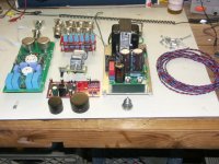
I have the LM317 and TIP50 heatsinked on a piece of aluminum flashing -- of course with Bergquist insulators, silicone grease etc.
An externally hosted image should be here but it was not working when we last tested it.
Jack, perhaps you could look real quick at the attached SPICE circuit. The reference designators align to those in LB-47. I'm using a single pass MOSFET. R3 had to be dropped significantly, but will be a 1/8W resistor, so it should still protect against over current. The RSET resistors should run much cooler.
Attachments
Jack, perhaps you could look real quick at the attached SPICE circuit. The reference designators align to those in LB-47. I'm using a single pass MOSFET. R3 had to be dropped significantly, but will be a 1/8W resistor, so it should still protect against over current. The RSET resistors should run much cooler.
Replace the 1N4733 with a 1N4739... (BV=9.1) should work then.
Jack,
Nice drawing, played around and checked my voltages they are where they should be.The R5 I had in there was significantly higher I noticed the pass transistor running much hotter than it is now, I will add some heat sinking any way. Case showed up today 12" X 12" X 3-3/4", a little tighter than I had imagined but doable. Any recommendations on signal grounding not sure what to do with transformer coupled inputs, I will use the ground loop breaker from amp ground to case/earth ground.
Thanks
Bill
Replace the 1N4733 with a 1N4739... (BV=9.1) should work then.
ah, of course the only thing I didn't change in the circuit 🙂 A 12V zener works well for both versions. I'll play around with it a bit more than post the changes.
ah, of course the only thing I didn't change in the circuit 🙂 A 12V zener works well for both versions. I'll play around with it a bit more than post the changes.
...and don't identify a net as NET_0...when you get to my exalted years you get to thinkin' that they young pup has just grounded the input of the LM317.
I mounted the power supply and amp their new home and powered it up, the neons glowed for a second and died down but no leds. Then I noticed no filaments in the 6SN7. Power it down and checked and cold solder joint re-soldered and and powered it up and everything lit up. Would have put some inputs and outputs on it and tested but no molex plugs to be found. Decided to ditch the molex plugs and solder silver wire for internal wiring (it deserves it) so had to ordered some wire. In the mean time a pair of Martin Login Electrostats followed me home today listening to some Buddy Guy - the grin on my face is starting to hurt.
Bill
Bill
Generally, I don't run traces for the filaments on PCB's -- preferring twisted pair -- these are high current traces which carry a lot of noise.
I use both silver and CAT-5 in my preamp.
I use both silver and CAT-5 in my preamp.
- Home
- Amplifiers
- Pass Labs
- ImPasse Preamplifier