I have 100 ohm on the gate, and 100K feeding it. I'm using 1N4742. Other than that, the same values on the first schematic of the brief.
Maybe try a 15-18V zener instead? And going up to 470R on the gate stopper couldn't hurt.
ok, I can try that zener change. Very strange though. My simulation is dead on... until things heat up 🙂
In other news, I got the board running. I dialed in the CCSes to 8mA then jumpered my test location and fired it up. First, the sea foam green neons came on then the four red LEDs... then the neons turned off. The overkill CCS heat sinks after 10 minutes or so were room temperature and the 12.5K series resistor seemed warm, but not overly so. At some point, I'm thinking about trying to cut this value in half and shift more heat towards the heat sinks.
I had a token bone headed move, in that I wanted to measure the input to the regulator, and despite my meter being in volts mode, I forgot to move the probe over 😱. After a little pop and spark, everything seemed to be fine. I had about 430V here, so I plan on adjusting my prereg circuit a bit. I'm assuming at idle this thing will draw it's maximum current.
Now, the sad thing is, I only have a F5, left by a friend to fix, with one good channel at the moment to test the thing. Hm. Kinda annoying.
In other news, I got the board running. I dialed in the CCSes to 8mA then jumpered my test location and fired it up. First, the sea foam green neons came on
then the four red LEDs... then the neons turned off. The overkill CCS heat sinks after 10 minutes or so were room temperature and the 12.5K series resistor seemed warm, but not overly so. At some point, I'm thinking about trying to cut this value in half and shift more heat towards the heat sinks.I had a token bone headed move, in that I wanted to measure the input to the regulator, and despite my meter being in volts mode, I forgot to move the probe over 😱. After a little pop and spark, everything seemed to be fine. I had about 430V here, so I plan on adjusting my prereg circuit a bit. I'm assuming at idle this thing will draw it's maximum current.
Now, the sad thing is, I only have a F5, left by a friend to fix, with one good channel at the moment to test the thing. Hm. Kinda annoying.
I would keep the 12k5 resistor as is. It has two functions- first, to spread the dissipation load around, but second, to isolate the CCS from the tube. I can't measure any ill effects from the CCS capacitances, but at least one very smart engineer (Brian Beck) does worry about that, so why not prevent any issue in the first place? For lower plate resistance tubes, I think that's not really necessary, but a 6SN7 is not a low plate resistance tube.
Which MOSFET are you using in the regulator?
Which MOSFET are you using in the regulator?
I would keep the 12k5 resistor as is. It has two functions- first, to spread the dissipation load around, but second, to isolate the CCS from the tube. I can't measure any ill effects from the CCS capacitances, but at least one very smart engineer (Brian Beck) does worry about that, so why not prevent any issue in the first place? For lower plate resistance tubes, I think that's not really necessary, but a 6SN7 is not a low plate resistance tube.
Which MOSFET are you using in the regulator?
The thought was that a 6K resistor would still have the same benefits, but allow me to shift some heat away from this resistor. I remember Jack saying this resistor gets pretty hot. Perhaps you're right though 🙂
The working regulator is using a pair of MJE13005. The one this is exhibiting the strange voltage dropping is using a single IRF840.
And going up to 470R on the gate stopper couldn't hurt.
wait, you have to connect both ends of the gate stopper?
yeah, that was it. Still strange it worked for 2 minutes though 🙂Well, Impasse barley made it to BAF I finished it the night before. and people seemed to think sound of Impasse and F4 were pretty good thought I should have played it on the better speakers later on. When I got it home and hooked everything back up and R5 (on Jacks schematic) or R105 on the original burned up. It was 20K 1/2 watt and as I understand should not have that much current flowing threw it. Any clues why it would burn up ?
Bill
Bill
Well, Impasse barley made it to BAF I finished it the night before. and people seemed to think sound of Impasse and F4 were pretty good thought I should have played it on the better speakers later on. When I got it home and hooked everything back up and R5 (on Jacks schematic) or R105 on the original burned up. It was 20K 1/2 watt and as I understand should not have that much current flowing threw it. Any clues why it would burn up ?
Bill
That resistor just supplies base drive to the pass transistor -- are you sure that the orientation of D103 is correct?
I reread your earlier post on the regulator and figured that, the d103 is oriented correctly. I used a cheap 1/2w metal film resister but in that position I would not think it maters. My unit has been ill behaved for about 5 seconds with tweeting noises until the voltage stabilized. I wonder if this is an indicator of something else going on, could there be an inrush issue? With solid state rectifiers you don't get the benefit of the soft start a tube rectifier would offer.
Thanks
Bill
Thanks
Bill
No obvious shorts, I will check the TIP50 I used, I have a spare. I will pull the power supply and replace the resister and bring it up slow with some load resisters checking voltage across regulator etc. In operation the heat sink on the pass transistor and regulate never got hot just warm. I will be out of town a few days this will interfere with my rem sleep. I have a party this weekend I am sure they will want to have a listen as if BAF was not enough pressure to get it running. The impression from the listeners from BAF was smooth with nice detail not a lot of bass but f4 are not noted for this. Funny on my home speakers I a have plenty of bass may have been the show speakers. Missed not meeting SI and Jack would have liked to thank you in person for support.
Bill
Bill
Bill
Bill
Last edited:
Missed not meeting SI and Jack would have liked to thank you in person for support.
I was just getting back from England at the time and was unable to make it. I wouldn't have had a lot to contribute anyway.
I learned one very important thing in England -- you can take your bottle of champagne into your box at the Royal Albert Hall.
Swamped out the TIP50 and everything measures and runs back to norm. It must have taken a spike, I think I will add a cl110 and a MOS device on the power inlet. Has anyone else had an issue with instability until power stabilizes?
Bill
Bill
I learned one very important thing in England -- you can take your bottle of champagne into your box at the Royal Albert Hall.
Last night prom's ? Really !!
Swamped out the TIP50 and everything measures and runs back to norm. It must have taken a spike, I think I will add a cl110 and a MOS device on the power inlet. Has anyone else had an issue with instability until power stabilizes?
Bill
Without a little bit of a heat sink the pass transistors sweat a lot.
I have a common heat sink with insulators. It runs warm, ran it for 4 hrs last night little resister never got warm, so it must have been a fluke. I will add some power protection anyway, as well as a time delay to mute output for 5 or 6 seconds. This one has tested my patience because I was rushing to get it to BAF. I rushed the front panel but it turned out OK , made from walnut to match F4s.
Attachments
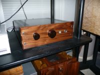
Getting there... a few "obvious" mistakes, but they'll get corrected soon enough. Haven't decided if I should put the transformers on top, on in the case, but I can accommodate both orientations.
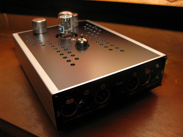
Getting there... a few "obvious" mistakes, but they'll get corrected soon enough. Haven't decided if I should put the transformers on top, on in the case, but I can accommodate both orientations.
If you have something like a weller soldering iron, or a hair blower, (a device which draws a lot of current) connect a 10K resistor across the primary, connect secondary to scope -- ground the can to your chassis and see how immune the the trafo is from interference by placing the power line close to the trafo. You can move the power cable about to see how well the shield works.
It's amazing that sometimes the best laid plans can get upset by a ground loop, bad shielding etc.
Sounds like a good idea. Do you have any experience with turning the input transformer around (secondaries are now the primaries)? I cannot remember where I read this, but I believe it was in the context of single-ended to balanced conversion. I should have researched this more to form a proper question, but perhaps you can fill in the blanks a bit?
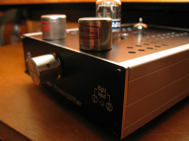
I also plan on doing some more testing with the Cinemags, as I don't believe anyone has come up with a suitable loading values for these (yet).
I also plan on doing some more testing with the Cinemags, as I don't believe anyone has come up with a suitable loading values for these (yet).
Last edited:
- Home
- Amplifiers
- Pass Labs
- ImPasse Preamplifier