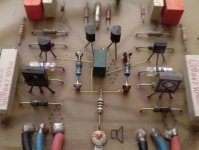
I referred to the circuit in post 67 which gives the value of R18 as 10R In farflungstars pictures this is at the bottom and in the middle of the circuit board with a black lead connected to a solder tag....
Ahhh... the plot thickens. The resistor is indeed 10R, which fits with R18. Yet it's in R17s position. (Note the shadows of the traces on the bottom of the board, highlighted in yellow in the attached image.)
Note also that Soundhappy's middle picture does indeed have both a R17 and a R18.
Attachments
An observation, I may have been imagining it but when I got the DC down (temporarily) the heatsinks seemed to give off a lot more heat - I hadn't noticed any heat rising from them until that point but they were obviously getting very hot. Similar to the heat that rises from an 845 tube.
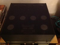
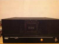
Your amp chassis doesn't have any through holes for air flow.
Source resistors are hot and probably more and more in closed box.....
Greetings 🙂
Source resistors are hot and probably more and more in closed box.....
Greetings 🙂
Yes I know. Maybe I could improvise some.Your amp chassis doesn't have any through holes for air flow.
Source resistors are hot and probably more and more in closed box.....
Greetings 🙂
Temperature stabilisation is very important factor for class A amplifier.Yes, I know. Maybe I could improvise some.
This takes some time normaly ~ 1hour.
With this very closed chassis they go hotter and hotter
so temperature is hard to stabilise and disaster can happen.

Actually last week I met a 'famous technician' and he told me he was working on a Hiraga. Must be the same amp. He told me in technical terms what he did to it. Guys name is PvW?
Jan
Hello,
My friend got back his Hiraga. The output was reduced but that isnt a problem for him but the sound was surely improved!!
He still uses the original caps. I think that 2 decades ago the quality of parts like caps was better. There were severaql brands that made real good parts. Now only a few left.
The Shinkoh resistors are way better than the ones used in most present Hiraga amps.
They dont use the original transistors so in fact they are not Hiragas.
The Hiraga needs proper cooling.
Me and my friend both used chokes in the power supply.
The 1K8 and the 0,47 ohm can both be improved.
Greetings, Eduard
Hello Eduard. Unfortunately my techie isn't a Hiraga expert but he can fix some things like the pots and change components. I'll get him to resolder all the bad joints.
Can someone tell me if the amp not being earthed is a problem and might in part account for the erratic DC?
Can someone tell me if the amp not being earthed is a problem and might in part account for the erratic DC?
You need to fix the earth as it's a safety issue.
But, no, it's not likely your erratic DC problem. I think that's the missing resistor (or possibly old and decrepit pots).
But, no, it's not likely your erratic DC problem. I think that's the missing resistor (or possibly old and decrepit pots).
Hello,
Tell your technician to use some kind of stand off to raise the heatsinks around15/20 mm or so.
Resolder? Maybe he should just cut and inch or so and make a '' fresh '' solderjoint.
Today someone at my company did check the complete electricity contact material with a Fluke temperature meter. There were some bad ones resulting in excessive heating.
Your amp probably needs a serious inspection. The 0,47 ohm and the resistors in the power supply are probably heating up parts in their surroundings.
Probably the people who build your amp did try to improve it but the execution is done in such a way that you end up with one not even close to the original Hiraga.
Greetings, Eduard
Yes I know. Maybe I could improvise some.
Oh no, don't do that. Your amp is absolutely stunning the way it is!
Look great YES !Oh no, don't do that. Your amp is absolutely stunning the way it is!
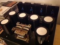
....well components on the pcb's need air flow
specially source power resistors run very hot inside of very closed chassis box.
After few hours they cook inside....
Attachments
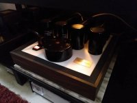
Look great YES !
....well components on the pcb's need air flow
specially source power resistors run very hot inside of very closed chassis box.
After few hours they cook inside....
There are no signs of overheating on the PCBs*. Cooking is good for Class A! 😀
Cheers,
Jeff.
* Most of the ageing appears to be from a failure to clean off the flux residue on the solder joints.
There are no signs of overheating on the PCBs*. Cooking is good for Class A! 😀
Cheers,
Jeff.
Hello,
You should read the original articles written by Jean Hiraga.He writes a lot on getting rid of the heat. Soundhappy is French and i can read French so we both did.
Greetings, Eduard
He he... you can probably tell from my avatar that I am not French (nor Irish, for that matter, though my wife is).
There are no signs of over heating on the PCBs but the two big resistors between the transformer and PCBs have scorched the the chassis so they must get very hot.
There are no signs of over heating on the PCBs but the two big resistors between the transformer and PCBs have scorched the the chassis so they must get very hot.
Yeah, that wouldn't worry me (marble can take a LOT of heat). But I do recognise that others might have different tolerances for this sort of thing.
Cheers,
Jeff.
There are no signs of overheating on the PCBs*. Cooking is good for Class A! 😀
Cheers,
Jeff.
* Most of the ageing appears to be from a failure to clean off the flux residue on the solder joints.
I guess this guy don't bias them in class A or was not use this amplifier for long session in the summer season.
Put 4 power resistors with high bias for 7 hours in such "box" chassais and things can go seriously problematic.
I have original Hiraga 20 watts version in my home and yeah 0.47R is going very hot but my have lot of air around so all is safe.
Btw i change for bigger wattage source resistors and they are on the open air side not in close box. Normaly you need all voltage's and current's from the schematic values match your Hiraga amp so all OK at this point.
I never see pure class A amplifier circuit in closed boxes why ?
Attachments
Hello, Then one day you come and you see this. The appartment is mine after a repair on the little roof with tar and a heater the '' spiderweb? '' in the dilation caught fire after the professionals left. House was filled with smoke, they rang my bell, nobody answered so they forced their way inside to check if nobody is there.
In my Thai hotel they have done the same . Only there the firebrigade took my camera gear on their way back home.
So please dont heat up things to much.
Greetings, Eduard
In my Thai hotel they have done the same . Only there the firebrigade took my camera gear on their way back home.
So please dont heat up things to much.
Greetings, Eduard
Attachments

There are no signs of over heating on the PCBs but the two big resistors between the transformer and PCBs have scorched the the chassis so they must get very hot.
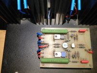
Yes i see braun colour and with all the wood around that is not safe and hard to temperature stabilise that is very important
Attachments
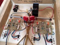
I can fix the internal heating problem - my priority is getting it working right so I can feel safe connecting my Tannoys: lolYes i see braun colour and with all the wood around that is not safe and hard to temperature stabilise that is very important
- Status
- Not open for further replies.
- Home
- Amplifiers
- Solid State
- Idiot seeks help with Hiraga