Yes they're both behaving weirdly. Could they be adjusting the bias for class A and having an effect on DC - or am I clutching at straws?Disregard my adjust-half-way-comment. I just looked at the picture again and realised there's only one pot per channel, not two.
That's some pretty flaky results then. Damage to the pot resistive tracks, perhaps? (Are they both really squirrelly?) It might be instructive to desolder one of them and put it on a multimeter and see if you get smooth resistance changes when rotating the screw.
The amp was built in the mid 80's and doesn't look it's been touched so I don't see why the pots should be so loose, they don't really need a screwdriver you can move them just by touching them with your finger.
I'll have another look tomorrow when I have some time.
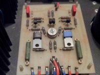
Note how the resistors on either side of the pot are in little carriers above the board so they can be changed without dismounting the board. I'd guess that they set the bias. The pot probably just adjusts the balance.
I looked at the schematic posted earlier, and those two resistors in little carriers control the amount of feedback, not the bias. The pot adjusts the feedback balance between the two push/pull output transistors. (If it works like the F5, changing that pot should adjust the amount of 2nd harmonic distortion.)
I'm a bit out of my depth here, but I think increasing the feedback will also decrease the bias current. So it might still be that the resistors-in-carriers also adjust bias, and that the pot would then also affect the DC offset.
I'm a bit out of my depth here, but I think increasing the feedback will also decrease the bias current. So it might still be that the resistors-in-carriers also adjust bias, and that the pot would then also affect the DC offset.
Balance? So not DC?
The potmeter is there for adjusting the offset.
Bias is fixed and relies partly upon the 12V supply and 1R collector resistors of the output transistors.
It's a little surprising that you have 0.47R resistors in your amp, but this may be due to a modified schematic.
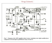
Here is a redraw of the original Hiraga 8W Monstre schematic:

Do you think that replacing the pots might fix the flaky readings?
I'm sorry for my last post. I showed the 8W Monstre but I here is the 20W redraw, showing, correctly, the 0.47R resistors!
The function of the potmeter, though, is the same.

The combined resistance of (R9+R10)||P1 determines the quiescent current together with the collector resistances of the output transistorsand and the supply voltage.
And from what you say, replacing the potmeter may be a good idea.
Thanks Morten - new pots it is.The potmeter is there for adjusting the offset.
Bias is fixed and relies partly upon the 12V supply and 1R collector resistors of the output transistors.
It's a little surprising that you have 0.47R resistors in your amp, but this may be due to a modified schematic.
Here is a redraw of the original Hiraga 8W Monstre schematic:
View attachment 642345
....
The combined resistance of (R9+R10)||P1 determines the quiescent current together with the collector resistances of the output transistorsand and the supply voltage.
Hi Morten,
So the resistors set the level of feedback and the bias, right? (I think this is what's called "current feedback", even though it isn't really?)
Thanks,
Jeff.
Hi Morten,
So the resistors set the level of feedback and the bias, right? (I think this is what's called "current feedback", even though it isn't really?)
Thanks,
Jeff.
I am on thin ice here...
But I think it may be a combination, since the value of R18 is only 10R.
The feedback is, as far as I can see, determined by R17/R18 = 20.
Ah, right. I think you are correct: R17/18 set feedback; R9/10 set bias. (Which makes much more sense, R9/10 being the ones that are "socketed".)
Cheers,
Jeff.
Cheers,
Jeff.
Thanks Morten - new pots it is.
This circuit will respond down to dc so adjusting the offset to zero will be more sensitive than one with a capacitor in series with R18 which in theory connects to earth - but which in fact connects to a ball of solder.
A properly made join does not look like this and does not have a dull finish which is what a cold solder joint looks like.
The problem is the join has not been heated properly - the reason for that is there is a lot more copper to transfer heat away from the join with heavier gauge wiring.
Apart from the dc offset adjustment, the connection is part of the negative feedback decoupling arm to earth and any anomalies in the signal transfer in that particular path will impact - negatively in this instance - on the quality of the feedback signal.
Correctly made solder joins have a shiny appearance. For that you need to remove the old solder and clean everything that has be soldered using new solder.
Doing so is a no brainer
So here's an interesting thing: from what I can tell there is no R18 in farflungstar's pictures!
R17: yep. And you can see the shadows of the traces leading from it to R9/10, and to the centre wiper of the pot. But no R18. Everything else on the board is accounted for.
Would a missing reference to ground explain the wandering offset?
R17: yep. And you can see the shadows of the traces leading from it to R9/10, and to the centre wiper of the pot. But no R18. Everything else on the board is accounted for.
Would a missing reference to ground explain the wandering offset?
Please see my old posts about trimmer and source resistors.
Idiot seeks help with Hiraga
Idiot seeks help with Hiraga
Could you verify how much hot are 0.47R source resistors?
Do they a lot's of heat?
All voltages are like on schematic: psu= 19V~ 21V, across 0.47R = 0.4 or 0.5V etc ?
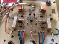
Photo in the middle are original Hiraga 20Watts amp circuit board 🙂
Idiot seeks help with Hiraga
Idiot seeks help with Hiraga
Could you verify how much hot are 0.47R source resistors?
Do they a lot's of heat?
All voltages are like on schematic: psu= 19V~ 21V, across 0.47R = 0.4 or 0.5V etc ?
Photo in the middle are original Hiraga 20Watts amp circuit board 🙂
Attachments
I'm sorry for my last post. I showed the 8W Monstre but I here is the 20W redraw, showing, correctly, the 0.47R resistors!
The function of the potmeter, though, is the same.
View attachment 642347
The combined resistance of (R9+R10)||P1 determines the quiescent current together with the collector resistances of the output transistorsand and the supply voltage.
And from what you say, replacing the potmeter may be a good idea.
I prefer these schematics over the one which has the 13V Zener diodes. I built both version to me the 20 or 22V (which is the 30Watt version) sounded much better.🙂 If I am right the one uses the 13V diodes was modified after by someone.
So here's an interesting thing: from what I can tell there is no R18 in farflungstar's pictures!
R17: yep. And you can see the shadows of the traces leading from it to R9/10, and to the centre wiper of the pot. But no R18. Everything else on the board is accounted for.
Would a missing reference to ground explain the wandering offset?
I referred to the circuit in post 67 which gives the value of R18 as 10R In farflungstars pictures this is at the bottom and in the middle of the circuit board with a black lead connected to a solder tag.
With a cold solder joint not all of the mass of the solder is heated evenly you are not excluding the possibility of erratic conduction which could be temperature and signal level dependent.
I just sorted one channel of a single-ended Class A amplifier with the same solder issue in the earth reference line. The dc offset in this one was 2 Volts.
The Hiraga is push-pull - and the voltage is wandering. I think the odds are that your hunch is correct.
So here's an interesting thing: from what I can tell there is no R18 in farflungstar's pictures!
R17: yep. And you can see the shadows of the traces leading from it to R9/10, and to the centre wiper of the pot. But no R18. Everything else on the board is accounted for.
Would a missing reference to ground explain the wandering offset?
farflungstar, you should check out R17 if it is really missing.
If it is, this amp will have higher gain, but how high, I can't tell.
Anyway, amps with no global feedback like the DarTZeel has an input stage with some similarities to the Hiraga 20W.
Here the midpont of R9/R10 is grounded and provides local feedback together with R11 and R12.
And there is no offset adjustment pot(!)

Interesting to know that the Hiraga 20W also works in non-feedback mode! (That is, if R17 is missing.)
Looking forward to hear more about this!
Looking into another DarTZeel schematic, it seems that the offset trim is done with a 50K pot (P1) at the input terminal.

I'll check if R17 is missing but I dont have much time today so it might be tomorrow. The amp does seem to go quite loud but of course that's subjective.
As I said earlier the amp has no earth at mains which I find surprising.
As I said earlier the amp has no earth at mains which I find surprising.
- Status
- Not open for further replies.
- Home
- Amplifiers
- Solid State
- Idiot seeks help with Hiraga