Ooops, I messed up the math slightly in my first post. It's actually two rails, with each of them feeding both channels. Still 2*2*1, but I forgot to double it for two rails.
So total PSU pi filter dissipation is 3 to 8 watts; total under the marble top is about 5 to 11 watts.
But still no toast. 😉
It's too many "maybe". Maybe his bias - 2A. 🙂 Maybe for him +55C is too hot. 🙂
Hello,
Tell your technician to use some kind of stand off to raise the heatsinks around15/20 mm or so.
Resolder? Maybe he should just cut and inch or so and make a '' fresh '' solderjoint.
Today someone at my company did check the complete electricity contact material with a Fluke temperature meter. There were some bad ones resulting in excessive heating.
Your amp probably needs a serious inspection. The 0,47 ohm and the resistors in the power supply are probably heating up parts in their surroundings.
Probably the people who build your amp did try to improve it but the execution is done in such a way that you end up with one not even close to the original Hiraga.
Greetings, Eduard
An accurate appraisal - if the wiring has been subject to heating due to resistance of cold solder joints some of copper will have been oxidised. This can be seen with the wire-wound resistors where these connect with the board.
I have observed that too heavy a gauge of wire makes solder joints more difficult. Oxidation of cable makes that job even harder. It can be seen what "improvement" going over the top with cable gauge can do.
The best way to deal with oxidised cable is to throw it away and replace.
I have doubt about your calculations of total amp heat dissipation.
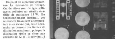
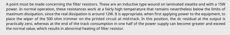
Hiraga write in this article 12 watts for 1R is real dissipation value so we use 15watts higher rated.
It's not my opinions . Dissipation réelle = real dissipation around ~ 12 watts.
I get strong practical side experience with this 20 watts amplifier.
I think more temperature , heat and air flow factor.
You need see long time amp service not only ah ok is not toast in fire for the moment.
Marble absort the heat but without air flow temperature stabilisation is problematic.
So write me who is drunk ? Ok you are the experts. Good luck !
Spend my energy to help this guy best i can.
Attachments
You don't see under the heat sinks are open space so air flow make natural convection of the power transistors stage.It's too much "maybe". Maybe his bias - 2A. 🙂 Maybe for him +55C is too hot. 🙂
Excellent Hiraga amp construction example.
I go drink mineral water now

Attachments
Hello,
He has been told to replace the resistors in the power supply with a Lundahl LL2733 choke. Two coils in parallel will create a nice 100mH 0,85 ohm choke. That will be a nice return on investment.
The pot to trim the dc is probably damaged. No need to have a 25 turns model. The Cosmos used in the original one was chosen for its sonics.
If you touch one of the driver transistors to make its temperature rise you will see dc ofset change!!
I think we better wait untill the original poster did ask his friend to do some serious '' maintenance ''on this amp.
Greetings, Eduard
...
Hiraga write in this article 12 watts for 1R is real dissipation value so we use 15watts higher rated....
He does indeed say that*. Not sure where he's getting it from. See attached LTSpice output. (I gave it pretty much the worst case scenario and it came out with about 4 watts per resistor.)
...
Spend my energy to help this guy best i can.
Yep, that's what we're here for too.
Cheers,
Jeff.
* Link to translated article: The Class-A Amplifier Site - Hiraga 20W Class-A
Attachments


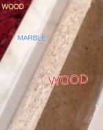
Diy version is made with composite wood, marble and 4 similar to Hiraga amp size heat sink.
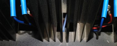
Original are all metal, heat sinks get a square opening (see on the photo ) for air flow, huge 15 watt resistors who run hot,
5 watt source resistors who run hot (actually 10W) .
I can put my hand for 5 second but in July is like 3s...
Conclusion :
change or heavy modify chassis to more heavy aluminium version for example.
Wood can be for the MC Step-Up and crossovers.
LTSpice models give me a break
Attachments

Hello,
The caps are kind of mounted with the screws meant to be used just for connecting the wires!!
The wires from the rectifier are very close to the wires for the primary side of the transformer.
I think i told him to use a smaller cap for each side + and _ put that one on the inside CLOSE to the rectifier then the choke and then the two final caps in parallel.
The first cap could be something like a Mundorf 33000µF 40 volt which is 35*60 mm. The original Hiraga did use 68000µF for the first cap but the higher this value the more the rectifier/transformer gets stressed and kind of '' radiates '' garbage.
You could easily hear the effect of replacing the 1K8 resistors with a 1K8 2K or 2K2 Allen Bradley 2 watt resistor. I did this 30 years ago and i still remember the impact.
Of course your amp has not been build with the original 1/2 watt Shinkoh tantal resistors. 30 years ago these were one euro a piece which was considered expensive then. Partsconexxion still has some Shinkoh stock. Right now i would not know which brand to use if i would have to build one. The transistors are obsolete too so i think i would go for a Nelson Pass design lol
So better ask your technician to order the chokes. First check if the LL2733 will fit. You need two. You could always put another bottom plate with two rectangular holes to create some extra space. These holes you can cover by a small rectangular plate mounted on 4 stand off.
If you pay postal services and provide a clear drawing i will use my CNC machine at work.
In the attachment you can see the new chassis i made for my home cinema amp. This will allow me to change parts without having to desolder the circuit because usually there will be all kind of connections to front and back plate.
Greetings, Eduard
Attachments

The output transistor sets are a complementary feedback pairs which have better thermal stability if the driver in each set is mounted on the same heatsink as the power device.
The output transistor sets are a complementary feedback pairs which have better thermal stability if the driver in each set is mounted on the same heatsink as the power device.
Interesting. I assume by driver/power device you mean each red circle on the same heatsink, rather than the blue circle, right?
Attachments
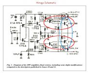
The way I look at this e.g. is if the temperature of 2SA 634 is allowed to increase it will pass more collector current through the 1.8k resistor connected to the negative supply rail. Accordingly the voltage drop across the latter will increase a little - so the base voltage applied to 2SD188 base will become more negative i.e. less positive as needs be since this will be running hot judging by the standing current which needs to be kept in check.
If 2SA 634 is located remotely inside the chassis it will take some time for the heat to get there as it eventually will. I don't see much ventilation to help reduce the build up of heat when it does.
There could be a phase when the 2SD188 is getting too hot for a period during warm up putting extra stress on such as wire-wound resistors in the process.
Last edited:
Each output transistor dissipates around 20 watt, thus 80 watt for the complete stereo amp. Imagine how hot an 80 watt soldering iron would be. So what exactly is the problem.
If the design was followed as intended by Hiraga, the transistors would stabilize at some temperature above ambient when the dissipated heat from the heat sinks are equal to that generated by the transistors.
There is no temperature compensation here, you must ensure that the heat sinks are adequate.
An observation, I may have been imagining it but when I got the DC down (temporarily) the heatsinks seemed to give off a lot more heat - I hadn't noticed any heat rising from them until that point but they were obviously getting very hot. Similar to the heat that rises from an 845 tube.
The dc offset is influenced by the gain characteristic of the complementary stages for each set in series from input to output. I looked at the English translation of the Hiraga article which covers this point and how to solder the Litz wire properly.
If you have a cold solder joint anywhere the fact that the complementary pairs have been matched for gain is no guarantee you will be able to reduce the dc offset to a satisfactory level.
Even if the natural dc offset - due to matching characteristics of the complementary transistors is low - that amount will be amplified by the negative feedback process.
Such an unwanted outcome might have been avoided by including a capacitor in series with the 100R resistor in the feedback decoupling arm to earth.
It appears in your case the dc difficulty has been overcome by removing the earth decoupling arm of the feedback network - if so this turns the circuit into a unity gain buffer.
From the Hiraga article the minimum recommended closed loop gain is about 150/100 plus 1.
This will increase the bandwidth a little without causing stability problems. Converting the amplifier to unity gain is taking that a risky step further.
If the heat -sinks get hotter while you are trying to adjust the dc offset it seems the stability is somewhat marginal - something you should investigate further.
Hello,
Putting a driver transistor and a power transistor on the same heatsink will surely reduce the lifetime of the driver if it will survive at all.
WHAT can be done is mounting the two drivers on the same heatsink ( OF course with thermo pads). If you '' heat up'' one of the drivers by touching it the dc output will change.
Did ask Guido Tent if his 15 volt shunts can be used instead of the 15 volt zenerdiodes.
We will see if the original poster will follow some ideas given here lol
Greetings, Eduard
- Status
- Not open for further replies.
- Home
- Amplifiers
- Solid State
- Idiot seeks help with Hiraga