I can fix the internal heating problem - my priority is getting it working right so I can feel safe connecting my Tannoys: lol
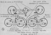
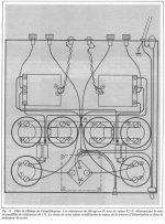
See this original article maybe can be useful about PSU schematic
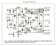
Hiraga 20W classe_A
~ 0 mV offset is not possible but no big deal because this is one amp with moderate 15 dB of feedback write Mr Hiraga.
R3/R6 need to bee 12K for correct offset value he say.
On non original schematic is 27K...
R3/R6 need to bee 12K for correct offset value he say.
On non original schematic is 27K...
Attachments
So if I can replace the pots a figure around 40mv should be okay?
Would the amp be better grounded?
Would the amp be better grounded?
I'm not sure why changes were made to the original. This wasn't put together by a diyer - it was done by the engineers at Expolinear, a German loudspeaker maker, and used to demo their speakers at shows.
~ 0 mV offset is not possible but no big deal because this is one amp with moderate 15 dB of feedback write Mr Hiraga.
R3/R6 need to bee 12K for correct offset value he say.
On non original schematic is 27K...
Schematic with 27K - it's original Hiraga's 20W from 1985 (L'Audiophile №34, jan. 1985).
With 12K - from 1980 (L'Audiophile №15, april 1980).
🙂
I'm not sure why changes were made to the original. This wasn't put together by a diyer - it was done by the engineers at Expolinear, a German loudspeaker maker, and used to demo their speakers at shows.
On en parle n°34 : modifs ampli Hiraga 20W, tweeter technics 5HH10 ...
Good point that was made for version with other output stage transistors so resistors change to 27K 🙂
What transistors get Farflungstar ?
What transistors get Farflungstar ?
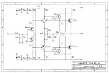
That looks like the circuit, the values look okay (r8/11 - 1.5k). The amp was built in 1983 (I think).
So if I can replace the pots a figure around 40mv should be okay?
Would the amp be better grounded?
40 mA is acceptable.
Always possible buy one cheap Welleman speakers protection kit module if you are very worry about Tannoys.
Make classic star ground connections. Take care about heat dissipation.
Kindest regards 🙂
Attachments
So what reference of power output stage transistors is ?That looks like the circuit, the values look okay (r8/11 - 1.5k). The amp was built in 1983 (I think).
2SD188 and 2SA627 or ??
The schematic shows 0.8 to 1.0A over each 0R47 source resistor. That's 0.4 to 0.5 watts each for a total of 1.6 to 2 watts.
The PSU pi filter uses either 0R5 or 1R (according to the article; I can't see farflungstar's well enough to tell what they are). So that's another 2 to 4 watts.
Throw in a bit more for the non-output transistors (the output transistors are outside the case on heatsinks), and we've got, what, 5 to 8 watts?
Sure the resistors will get hot; sure localised heating may discolour the marble. But you couldn't even make toast inside this thing with 5 to 8 watts.
Cheers,
Jeff.
I don't know - but will look tomorrow.So what reference of power output stage transistors is ?
2SD188 and 2SA627 or ??
Without air flow in such closed space they can't stabilise easyly they get hotter and hotter with time.
Compare theory to the real amp in action...your amplifier.
Yeah ? What we read on the psu schematic ?
It's 2x15 = 30 watts for this two resistors only
Take care 🙂
Compare theory to the real amp in action...your amplifier.
The PSU pi filter uses either 0R5 or 1R (according to the article;
I can't see farflungstar's well enough to tell what they are).
So that's another 2 to 4 watts.
Yeah ? What we read on the psu schematic ?
It's 2x15 = 30 watts for this two resistors only
Take care 🙂
That looks like the circuit, the values look okay (r8/11 - 1.5k). The amp was built in 1983 (I think).
Maybe you have 30W version? Check another resistors (12K, 27K or 33K placements).
What's BJTs you had used? 🙂
my small Hiraga 20W 🙂
http://www.diyaudio.com/forums/solid-state/96192-post-solid-pics-447.html#post4568264
Without air flow in such closed space they can't stabilise easyly they get hotter and hotter with time.
Compare theory to the real amp in action...your amplifier.
Yeah ? What we read on the psu schematic ?
It's 2x15 = 30 watts for this two resistors only
Take care 🙂
OK let's counting 🙂
P=IIR I=1A R=1 omh, two channels, one psu. 2*2*1=4W per res.


...your amplifier.
Hey, I like the sound of that. 😉
Yeah ? What we read on the psu schematic ?
It's 2x15 = 30 watts for this two resistors only
Take care 🙂
That's the resistor rating, not what it actually dissipates. Dissipation is R x I^2. (Higher rated resistors than required are sometime used because they have lower flicker noise.)
Hey, I like the sound of that. 😉
That's the resistor rating, not what it actually dissipates. Dissipation is R x I^2. (Higher rated resistors than required are sometime used because they have lower flicker noise.)
Maybe he a little drunky?.. 🙂
OK let's counting 🙂
P=IIR I=1A R=1 omh, two channels, one psu. 2*2*1=4W per res.
Ooops, I messed up the math slightly in my first post. It's actually two rails, with each of them feeding both channels. Still 2*2*1, but I forgot to double it for two rails.
So total PSU pi filter dissipation is 3 to 8 watts; total under the marble top is about 5 to 11 watts.
But still no toast. 😉
- Status
- Not open for further replies.
- Home
- Amplifiers
- Solid State
- Idiot seeks help with Hiraga