If the signal is correct without the DAC, then I would suggest you check the pins of both bottom and top GPIO connectors of the DAC, trying to find any disconnect pins.
Ian
Checked. All pins conduct.
I recently swapped from the IVSTD to a trafo output stage using Ians board and the Chinese trafos. I seem to have developed a ground loop in doing so.
The build is kind of double insulated in that there is no connection to PE to any of the component inside the (wooden and plastic) box.
I thought I'd try adding a wire from signal ground on the trafo pcb to the PE at the IEC and no change.
Any thoughts. ? I know when I built my brothers Ian Canada streamer using trafo output but not using Ians PCB......I had a ground loop hum when using the CT of the trafo for balanced XLR. Disconnected the CT and used SE rca and all.was.well.
Not as easy to try on Ians board and I am SE.
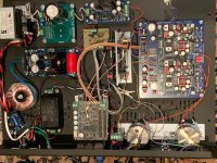
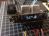
Just finished DDDAC with Ian's Q3 FifoPi board, Neutrino2 clocks, Jensen transformers:
Lovely build!
Just finished DDDAC with Ian's Q3 FifoPi board, Neutrino2 clocks, Jensen transformers:
Very good!
Please tell, do you have a signal from Neutrino2 clocks to FifoPi 5v or switched to 3.3 v?
@ Anta
DATA and LRCK signals are reversed. You need to change the DAC settings.
For my HDMPpi MKII, please refer the schematic of the HDMI connections
DocumentDownload/HDMIpiMkIITransmitterV2.0.pdf at master * iancanada/DocumentDownload * GitHub
Regards,
Ian
DATA and LRCK signals are reversed. You need to change the DAC settings.
For my HDMPpi MKII, please refer the schematic of the HDMI connections
DocumentDownload/HDMIpiMkIITransmitterV2.0.pdf at master * iancanada/DocumentDownload * GitHub
Regards,
Ian
Hello,
I´ve following configuration:
- KHADAS VIM3 (Krescue) + VOLUMIO
- to I2SoverUSBVsIII over USB
- to Ian´s dual mono DAC HAT (using flying wires) + plugged ESS controller
- with passive transformer I/V
- to WHAMMY HPA
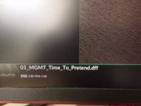
I could play DSD up to DSD256 (green LED shows locked DAC).
If I´m trying to play PCM both DAC unlocked: ESS controller shows right values but only clicks to ear.
Automute selection or OSF bypass don´t change anything.
Changes to PC with Audirvana, same results!
So not an software application issue.
Replacing Ian´s dual mono DAC HAT by Chinese single ES9039Q2M DAC and I´ve no problems with playing DSD or PCM: DSD512 and PCM 384kHz.
I don´t know what´s wrong?!
Did someone have an idea what´s the mistake?
Thanks,
JP
I´ve following configuration:
- KHADAS VIM3 (Krescue) + VOLUMIO
- to I2SoverUSBVsIII over USB
- to Ian´s dual mono DAC HAT (using flying wires) + plugged ESS controller
- with passive transformer I/V
- to WHAMMY HPA
I could play DSD up to DSD256 (green LED shows locked DAC).
If I´m trying to play PCM both DAC unlocked: ESS controller shows right values but only clicks to ear.
Automute selection or OSF bypass don´t change anything.
Changes to PC with Audirvana, same results!
So not an software application issue.
Replacing Ian´s dual mono DAC HAT by Chinese single ES9039Q2M DAC and I´ve no problems with playing DSD or PCM: DSD512 and PCM 384kHz.
I don´t know what´s wrong?!
Did someone have an idea what´s the mistake?
Thanks,
JP
@JP
Did the ESS controller show the correct PCM and Fs numbers when you play PCM?
To understand your system, can you post a picture showing the connections?
Ian
Did the ESS controller show the correct PCM and Fs numbers when you play PCM?
To understand your system, can you post a picture showing the connections?
Ian

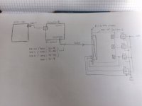
Usually LRCK shares the same pin with DsdL, but it's different in your drawing. Please confirm real LRCK signal is connected to PIN35 of GPIO.
And I saw the wires are too long for I2S signals, I don't think it's capable of the high Fs music such as 384KHz.
Ian
And I saw the wires are too long for I2S signals, I don't think it's capable of the high Fs music such as 384KHz.
Ian
verified, confirmed:
- I2SoverUSB H3-11 to J3/7-12 (BCLK_I2S --> SCK)
- I2SoverUSB H3-13 to J3/7-40 (DATA-I2S --> SD/D2)
- I2SoverUSB H3-15 to J3/7-35 (LR-CK-I2S --> LRCK/D1)
JP
- I2SoverUSB H3-11 to J3/7-12 (BCLK_I2S --> SCK)
- I2SoverUSB H3-13 to J3/7-40 (DATA-I2S --> SD/D2)
- I2SoverUSB H3-15 to J3/7-35 (LR-CK-I2S --> LRCK/D1)
JP
Hello guys,
problem solved: reducing wire lengths and added wire for 3.3V from pin 1 to pin 17.
Would be very helpfully to have the schematics.
JP
problem solved: reducing wire lengths and added wire for 3.3V from pin 1 to pin 17.
Would be very helpfully to have the schematics.
JP
Congratulations JPS64. What was the approx length before and after. Good for us all to know the limits.
Hello guys,
problem solved: reducing wire lengths and added wire for 3.3V from pin 1 to pin 17.
Would be very helpfully to have the schematics.
JP
@JP
I'm glad you fixed the issue. For any signals above 1MHz, we have to think them in the RF way. Wire length, grounding, shield and cross talk, impedance matching are all needed to be taken into account.
Regards,
Ian
- Home
- Source & Line
- PC Based
- IanCanada's Latest RPi GB Goodies Impressions... and your tweaks, mods and hints...