A picture of stationPi pro from earlier thread. I am also eagerly awaiting release 🙂 maybe Ian will make a group buy with bundle options?Thanks allot Caleb ! this has helped me heaps! appreciate having this pointed out.
Ian, any update on when the new station pi is going to be released ? any teasing pictures ?
Fifopi has changed my listening experience! Thanks for such a great product.
Attachments

Anyone been using raspberry pi 4b as a music server using Ethernet connection to network switch for the streamer to find through upnp, if you connect fifopi will it reclock the signal before going out by Ethernet?
SSD with music files
raspberry pi 4 with LMS
fifopi hat clock
ethernet out (or WiFi out)
will the fifopi clocks do their magic or must it be connected to transportpi to work?
SSD with music files
raspberry pi 4 with LMS
fifopi hat clock
ethernet out (or WiFi out)
will the fifopi clocks do their magic or must it be connected to transportpi to work?
HI Stephan,
I am using mini LifePO4 3.3V with success for a couple of weeks, but single and only in Pure mode. I tried it with UCconditioner and without UC conditioner and both set ups work. The LifePo4 battery I got were precharged, so I got straight 3,25V out on Pure mode. I 24/7 use an adapter 2,2A with 5,5Volt. I did not seperately tested rechargemode/non Pure out. May next week I have time to check this.
I am using mini LifePO4 3.3V with success for a couple of weeks, but single and only in Pure mode. I tried it with UCconditioner and without UC conditioner and both set ups work. The LifePo4 battery I got were precharged, so I got straight 3,25V out on Pure mode. I 24/7 use an adapter 2,2A with 5,5Volt. I did not seperately tested rechargemode/non Pure out. May next week I have time to check this.
Hello,
I guess we will have to wait for Ian.
If during switching the relais will be '' stressed '' by to much current it will in the end make the quality of the supply go down. You will caps with extremely good specs that will work like pretty normal caps because the relais will be the bottleneck.
If i am right Ian's ultracap circuit are designed with '' protection '' to limit the current so there should be no excessive stress on the power supply ( supplying the current) and the relais.
Greetings, Eduard
@Ian, Hate to keep bugging you.. 😉 Any word or status when the StationPi Pro will be available for purchase? Eagerly waiting for it for my next project.A picture of stationPi pro from earlier thread. I am also eagerly awaiting release 🙂 maybe Ian will make a group buy with bundle options?
Happy Holidays my friend,
Rick
Bumping, can anyone help with the question if you know or have tried this?Anyone been using raspberry pi 4b as a music server using Ethernet connection to network switch for the streamer to find through upnp, if you connect fifopi will it reclock the signal before going out by Ethernet?
SSD with music files
raspberry pi 4 with LMS
fifopi hat clock
ethernet out (or WiFi out)
will the fifopi clocks do their magic or must it be connected to transportpi to work?
Daniel, I am pretty sure, this is not the case. All the reclocking happens independently of the pi after the pi and is not fed back into it.
Hello,
I'm going to try UCPURE for my Pi2AES but can't quite understand in which way it can be switched from stock 3,3V to 5V. In data sheet mentioned jumper settings with 21K 0603 1% and 11K 0603 1%. Does it mean I should solder two resistors in order to switch to 5V? Can I buy it in 5V form already?
thanks
A RPi gets it's digital stream FROM the ethernet connection. A DAC hat, or USB DAC (both after reclocking) are then used to convert the digital stream to analog audio going into your system.Bumping, can anyone help with the question if you know or have tried this?
Hi
Does anybody know when the next GB is available or is it still possible to add ordres to the last updated ordre reply in this thread?
Would really like to add the StationPi Pro and some other stuff the order...
Any update on the Station Pi Pro please? 🙂
/Mikkel
Does anybody know when the next GB is available or is it still possible to add ordres to the last updated ordre reply in this thread?
Would really like to add the StationPi Pro and some other stuff the order...
Any update on the Station Pi Pro please? 🙂
/Mikkel
I'm not sure if this point has been discussed previously. I need a clarification regarding the activation of two UcHybrid 3.3v board with two maxwell ultra cap to put on top on LiFePO4 MKii
In the manual of the UcHybrid board i see that i've only to solder the caps on the board and to solder the two wires on the bottom of LifePO4 (respecting the battery polarity: red with positive and black with negative).
After that i can put the battery cells in the cells holders, wait 20 minutes to charge the cap and then i can turn on the LifePO4 borad upgraded and use it
Are all steps correct ?
I'm asking because I remeber that in a previous discussion a pre charge phase (using a power resistor) for the ultra cap was necessary to avoid demage at the LifePO4.
This phase is not usefull anymore ?
Thanks for the Ian reply. The reply is listed below for reference,Dear Ian /Folks,
There is an inquiry on option 3.3v DC input for 'HDMiPi Transmitter' and 'HDMIPi Receiver'. Please refer to below for the details.
For the 3.3v direct-connected upgrade option- 'HDMiPi Transmitter':
1a: Which in and out should be bridged together? Since there are 'in /out' pins on the '3.3v regulator board' and ''in /out which nearby C24 position.
1b: once L1 removed and bridged the 'in /out' together. Does the last step is to connect the 3.3v DC input into the J3 terminal block?
1c: Is any conflict when directly connecting the 3.3v input into 'HDMIpi Transmitter' which stack on the 'FifoPi Q3'. In this case, the 'HDMIpi Transmitter' is stacked on the 'FifoPi Q3'.
For the 3.3v direct-connected upgrade option- 'HDMiPi Receiver':
2a: Which in and out should be bridged together? Since there are 'in /out' pins on the '3.3v regulator board' and ''in /out which nearby C12 position.
2b: once L4 removed and bridged the 'in /out' together. Does the last step is to connect the 3.3v DC input into the J8 terminal block?
Thanks.
--1a: Which IN and OUT should be bridged together? Since there are two sets of in /out pins on the '3.3v regulator board' which is nearby the C24 position.
Any. But I recommend positionB.
--1b: Once L1 removed and bridged the 'in /out' together. Does the last step is to connect the 3.3v DC input into the J3 terminal block?
Yes.
--1c: Is any conflict if directly connecting the 3.3v input into 'HDMIpi Transmitter' which stack on the 'FifoPi Q3'. In this case, the 'HDMIpi Transmitter' is stacked on the 'FifoPi Q3'.
If you didn't remove L1, the HDMIpi DC input will connect together with the power supply of FifoPi Clean side.
--2a: Which IN and OUT should be bridged together? Since there are two sets of in /out pins on the '3.3v regulator board' which is nearby the C12 position.
Any. But I recommend positionB.
--2b: once L4 removed and bridged the 'in /out' together. Does the last step is to connect the 3.3v DC input into the J8 terminal block?
Yes.
OK, I'm utterly confused.
I'm trying to put together a streamer to stream with Volumio. I am doing this now with only a Pi4B and a wall wart. I feed the Pi USB directly into the DAC of my amp. Herein lies the problem I need to address. The built in DAC, although a bit of an expensive affair, appears to be synchronous. I won't go into the appear bit.
I've decided to do what I do understand first. So I've purchased a suitable 2x6V secondary toroid, a dual LinearPi and a stationPI and screwed everything to a plank with an on off switch and a fuse on the 230V. Works.
I have a Pi to install to the StationPi.
I can't for the life of me figure out the next step in the process : what do I need to get (that is obviously compatible with the Pi4 and the StationPi to clean up the USB so I can feed a good signal to the DAC ?
There's simply to much stuff around, I can't make heads or tails of it.
Please help, or direct me to a source that can make me figure it out.
Thanks,
Pete
Hi,
is it possible to connect two 5V UcConditioner in series on the input and the output side? To get 10V at the output and to use only one 10V power supply as a source?
I've found someone using two 5V UcConditioner in series on the output side to get 10V output, but he is using two 5V supplies at the input side. This seems to work fine. But I just want to use one 10V supply on the input side.
Thanks, Michael
Hello,
The person doing this is Supersurfer and very close to this post, if i remember correctly he confirms it can only be done with each 5 volt board having its own separate power supply.
Greetings,Eduard
The person doing this is Supersurfer and very close to this post, if i remember correctly he confirms it can only be done with each 5 volt board having its own separate power supply.
Greetings,Eduard
@Cerole@A123
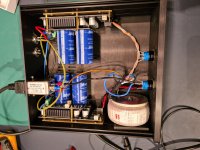
here my modifications of the TransportPi
I like your modification of TransportPi, where do you get the adapter of that SPDIF transformer?
Hi,Hi,
is it possible to connect two 5V UcConditioner in series on the input and the output side? To get 10V at the output and to use only one 10V power supply as a source?
I've found someone using two 5V UcConditioner in series on the output side to get 10V output, but he is using two 5V supplies at the input side. This seems to work fine. But I just want to use one 10V supply on the input side.
Thanks, Michael
I use 2 linearpi’s connected on 2 secondary 6v windings of a transformer, on output side they are in series to put out 10v. Works perfectly.
Attachments
- Home
- Group Buys
- Ian asynchronous I2S and S/PDIF FIFO KIT group buy