I think I stick with a Vbe multiplier, that is quite more easy and do work fine also keep bias on a stable level. The autobias systems are not much used, and when used quite protected.
Wise enough!

I did send mail but do not go to you, I do not now why.
here it is the answer there from me.
I do now when I put two low impedance 6 volt windings to each other I get 220v in and 220v out, I need a line input who do faseshift also and impedance 600 ohms or more. One winding on a current transformer do not be such high, the circlotron where it is needed for is a allfet version with fet input, make in unbalanced in the process.
If you stack 2 toroid coils with say 80 Henry and connect them by a single closed turn you will get a transformer with couple of windings, 40 Henry each. You can take different sensors with different inductances if want an other than 1:1 ratio. Or stack more than 2 of them.
https://www.facebook.com/Wavebourn/...1503329574641/485471831511123/?type=3&theater
I did see the coil of you where you complain that something alse has to be done for the closed windinds, you mean weh use this for halving the inductance and see it as one with just some windings that do work as a wideband transformer for audio use, I need single input and balanced output to make opposite fase, now I did ith with burr brown opamps (opa604).
The plastic current transformers looks more difficult then a open toroid.
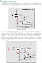
As for the auto bias, in the article here she do use diodes when she go conduct the autobias is effective disconnected.
Here some more explaining how it is done with tube stages, a circlotron is extra difficult because of floating character anf swing signal is present everywhere.
https://www.tubecad.com/2005/May/blog0045.htm
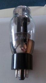
This tube can also drive big cap mosfets like irfp250 and such, I did see the rem 3200 amp has 300 watt 800 amp mosfets in it and drive them with tubes in dc coupled fashion, I have doubts that a nanofarads input capacitance needs a lot more then a tube can provide, so very strange the amp get,s so low in distortion, a way can be like I did a Sziklai pair kind, a 6AS7 is much more beefy however to drive but not enough for such mosfets for motor driving..
regards
Thanks for info.
regards
Attachments
Last edited:
What happens with nanofarads when they are bootstrapped by say 0.98 ratio?
Bigger soldering iron was needed. 🙂
And a copper foil.
I did see the coil of you where you complain that something alse has to be done for the closed windinds,
Bigger soldering iron was needed. 🙂
And a copper foil.
Last edited:
What happens with nanofarads when they are bootstrapped by say 0.98 ratio?
Bigger soldering iron was needed. 🙂
And a copper foil.
There happens also a lot with them as I usea low ohm resistor between gate and source, so it discharge fast, but still it need charged fast enough, nC is involveld in calculations how much peak to peak current is needed for that, most smps has tricks for that, like bjt network for fast charge discharge, however we talk about audio here, so it is low distortion sinusoidal waves.
Maybe SIC mosfets are something to use, I did think about it using them if she get some cheaper to test them.
I use a extra mosfet for convert capacity to pF range in amp who can drive the big mosfet easely without bootstrapping, like the Sziklai pair I did use, here I have also not loosing signal but has more capacity because of drain follower but it is 100 % feedbacked so miller is ruled out.
I have seen your coil, you say I need more stacked cores and connect them magnetically with a shorted winding evenly distributed around the core (as yours) who do also widening bandwidth? so for me when I need a balanced to unbalanced version I ave to use 3 cores, with two connected middle wires so I have three for balanced output.
a SIC module. (example)
http://www.farnell.com/datasheets/1670922.pdf
Has a nC of 490 9.5 nF so need a beefy driver.
regards
Last edited:
Did sim your coil idea, if I did it right I do not now.
I have mother in hospital who has a stumach bleeding after some weeks there, so busy with mine 85 years old mother, I do things between my spare time.
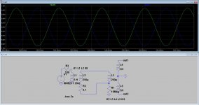
I have made a schematic witih three stacked coils and magnetically connected with a single winding idea.
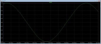
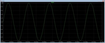
However I do loose signal on the 30 Hz region and below..
picture two is on 50 Khz, and I see it do from 1K to there very nice, but under 800 Hz it drops signal, on 20 Hz just to 200 mV
regards
I have mother in hospital who has a stumach bleeding after some weeks there, so busy with mine 85 years old mother, I do things between my spare time.
I have made a schematic witih three stacked coils and magnetically connected with a single winding idea.
However I do loose signal on the 30 Hz region and below..
picture two is on 50 Khz, and I see it do from 1K to there very nice, but under 800 Hz it drops signal, on 20 Hz just to 200 mV
regards
Attachments
Last edited:
What 0.1 Ohm? Where did you get it?
And 2.5 Henry is loo small inductance for 100 Ohm. The coils that I use have inductance 50-90 Henry.
And 2.5 Henry is loo small inductance for 100 Ohm. The coils that I use have inductance 50-90 Henry.
Last edited:
What 0.1 Ohm? Where did you get it?
And 2.5 Henry is loo small inductance for 100 Ohm. The coils that I use have inductance 50-90 Henry.
The 0.1 ohm is because LTspice complaine about short coils,' and needed a serie resistor, I did just drawn a idea to let you see if I right, the small indcutance is a shorted winding like you did to get signal over to the other coils, so high to low and low to high again.
I did not now how high the inductance was of the current transformer, so I did guess that.
regards
You mean 100 Hz and not 100 Ohm?
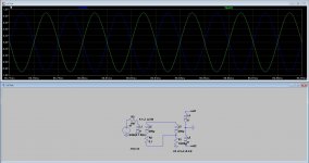
I did some more tests, but take in account that I did use perfect coupled coils, in reality things like capacitance and such things will degrade the transformer.
When I do use a couled winding who is 1 H then the coil do work from 10 Hz to 100 Khz in sim afcouse.
I did desolder a current transformer from a smps magnetron supply, these was one winding and 5 H winding, normal tranformer not usable afcouse can not stack them.
What happens if I do wind the shorted coil and short circuit them, did you use just one winding? in sim it did work see pictures, I think, it is sim.
Have the current transformers much windings or are that high permabillity toroids, I have a lot of them here in much colors.
On pictures it has on all freq a 1 : 1 output, without loose something but that is not real in praktice. The idea behind is very clever Wavebourn, that works very nice
in sim even better then jenson, on sim that is.
regards
regards
Attachments

Last edited:
I did make the resistor 0.1 ohm 0.0001 ohm, it was needed, and that give a lot better result on 20 Hz, I can now lower the single winding to 100 uH and with 3 henry coils I are close to wished result so 50 henry is quite overdone already making maybe impedance to high.
Changing couple factor in LTspice do however give losses very fast.
regards
Changing couple factor in LTspice do however give losses very fast.
regards
Last edited:
There are quite a lot different types of transformers, a 1:750 one has 1.2 Henry so how do you come to 50 henry? then we talk about 1 : 40.000 or such.
Oke I want to order some and play with it.
Frequency Response
As has already been discussed, the low frequency rolloff of the transformer is a function of the
primary inductance. A high inductance factor core is desired bec
ause of the low number of
primary turns. As the inductive reactance of the primary decreases with decreasing frequency, it
will effectively shunt an excessive amount of current away from the series AC current sense
impedance as frequency decreases.
As
for the high frequency rolloff of a current sense transformer, there are
both positives and
negatives
to this type of design. On the
positive
side, coupling between primary and secondary
is usually good, so leakage inductance is relatively low. On the
ne
gative
side, the turns ratio of
these transformers tends to be high
which
causes a relatively large shunt capacitance to appear
across the primary. It is the distributed capacitance of the secondary winding reflected into the
primary. The reflected capac
itance varies with the square of the turns ratio.
2
n
C
C
s
p
⋅
=
The larger the value of
C
p
, the lower the high frequency rolloff of the transformer. It begins to
shunt current away from the
Z
sa
c
element as frequency goes up and reactance goe
s down.
Transient or Pulse Response
The curr
ent sense transformer will respond adequately to pulse or transient type currents.
Leakage inductance and shunt capacitance tend to deteriorate transient response. The leakage
inductance of a toroidal unit
using a high perm
eability
core is relatively small. The shunt
capacitance at the primary is not large except for very high turns ratios.
With a unipolar rectangular pulse of current applied through the primary, a unipolar rectangular
voltage pulse is
developed across
Z
sac
and a calculation of the resulting flux density change
(?B)
in the core material can be calculated on the basis of voltage.
Last edited:
I did read also that it are high permiability cores what is used to get low stray inductance and capacity who is needed for a current transformer, this can be advanced for audio?.
There are much different types so what did you use as best option?.
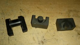
I have also this EP17 cores, somewhere on diyaudio is a thread about that for making a
line transformer.
PS can diysite remove the text on previous post? did work out wrong.
There are much different types so what did you use as best option?.
I have also this EP17 cores, somewhere on diyaudio is a thread about that for making a
line transformer.
PS can diysite remove the text on previous post? did work out wrong.
Attachments
I have order them, but do not now the inductance, so if you have experiment with these then it will be oke.
I have order them, but do not now the inductance, so if you have experiment with these then it will be oke.
~40-90, very inconsistent cores. But no need to match; you'll get an average result for both coils any way.
https://scontent.fsnc1-1.fna.fbcdn....=d9088c0571b41ac1a0afba6fbdd76648&oe=594CAEB1
Last edited:
~40-90, very inconsistent cores. But no need to match; you'll get an average result for both coils any way.
https://scontent.fsnc1-1.fna.fbcdn....=d9088c0571b41ac1a0afba6fbdd76648&oe=594CAEB1
Thanks for all your help, I keep you informed.
regards
Better Core perhaps?
This one seemed like direct factory sales. TA1075-75A-75mA-Through-hole-type-precision-current-transformer | eBay. Claimed 0.1% linearity, usable for 20 Hz - 20KHz and nanocrystalline core. Hopefully use cores with more consistency. More expensive though.
... very inconsistent cores. ...
This one seemed like direct factory sales. TA1075-75A-75mA-Through-hole-type-precision-current-transformer | eBay. Claimed 0.1% linearity, usable for 20 Hz - 20KHz and nanocrystalline core. Hopefully use cores with more consistency. More expensive though.
This one seemed like direct factory sales. TA1075-75A-75mA-Through-hole-type-precision-current-transformer | eBay. Claimed 0.1% linearity, usable for 20 Hz - 20KHz and nanocrystalline core. Hopefully use cores with more consistency. More expensive though.
The question is, what inductance of 1,000 turns on such a core?
You need to wait for a couple of weeks for the answer since the items I bought are still in shipment.The question is, what inductance of 1,000 turns on such a core?
The question is, what inductance of 1,000 turns on such a core?
If the claim that she do go from 20 Hz do mean she have high inductance, but I thought I have seen also somewhere , the easy thing is also it can put on pcb easely.
So I wait for Indra what he get,s🙂 and in the meanime wait until mine are here from shipment, the ones wavebourn did advice.
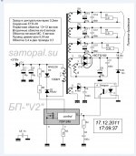
Ohh Wavebourn you can read russian, can you translate for me the little piece of tekst on the picture about the windinds, I am busy with build a inverter for the mig welder,
is better then transformers the normal way, and she are broken also.
Attachments
Last edited:
- Status
- Not open for further replies.
- Home
- Amplifiers
- Tubes / Valves
- Hybrid amp