In simulations the tube models can possible be not accurate, or better do count on it.
much difference, but do try when I have time.
regards
much difference, but do try when I have time.
regards
I know and particularly for the Russian ones as in my amp.
You could try some western tube such us 6SJ7 as pentode and 6CG7 as triodes.
These tube are the best substitutes in this design.
You could try some western tube such us 6SJ7 as pentode and 6CG7 as triodes.
These tube are the best substitutes in this design.
I have tryed it but I think it do not so well, why feedback when the amp has such low openloop, do not work, distortion without it is the same or even lower.
I have try also a fet driver, this do make high impedance for drivers, driving bjt with tubes do not go well most of the time, except when use super emittor follower.
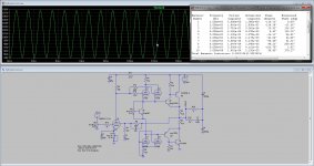
the driver tubes has 750 ohm plate resistors, quite high with such low anode voltages.
regards
I have try also a fet driver, this do make high impedance for drivers, driving bjt with tubes do not go well most of the time, except when use super emittor follower.
the driver tubes has 750 ohm plate resistors, quite high with such low anode voltages.
regards
Attachments

Thank you
The feedback here is is used the most for to take offset stable on Zero and I know that it does not make so many difference about distortion.
You are right about the 750 resistors. This was the value of the firs tentative: after I choose 330 Ohm, but I forgot to correct the schematic I published. Sorry.
I noted that Sziklai BJT output stage offer a higher input impedance and require a lower quiescent current. It really didn't seemed to me that the tube driver had problems to drive it.
In the first tentative I used also mosfet, but I noted that was too much easy to burn up them on the higher picks of the audio driving signal. So I decided for BJT.
Any way: if the percent of the distortion I see on the graphics you posted is near to the reality, I have to confess that I am satisfied.
Thanks again for your time.
Just curious, why do you use two coupling capacitors on the output (one goes to 200V and one goes to GND)? Why not just one? PSRR reason?
Exactly.
In reality it does not change so mauch....and in any way you will have to insert a second cap after the rectifier bridge, so you will not save neither money.
The signal has to cross the electrolytic caps in the power supply unit in any way. Also in case of a dual power supply unit with central tap secondary winding in the transformer.
The only solution for this problem is to adopt bridge power output stages, but everything has to be doubled....
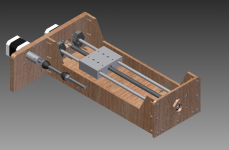
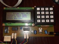
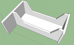
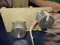
The system for winding coils is begun, because now it is holiday here it is some more difficult to get parts, in some weeks holiday is over and we can start, the electronic design and software is diy, not made by me but it is an nice start and have the program in C.
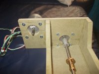
I have also a ohter version with only a hex file but do look very nice, see picture 3. These is made by Mike Webb, seems that all is gone now because I did not find more about this guy like a further development.
I have also a ohter version with only a hex file but do look very nice, see picture 3. These is made by Mike Webb, seems that all is gone now because I did not find more about this guy like a further development.
Attachments
Last edited:
High All, Soon I go start again, mother is oke again, and winter comes, so I do much more inside, first make the winder, then amps.
These winder is not mine design, but a free one from the internet, I can not program pic's and such.
regards
These winder is not mine design, but a free one from the internet, I can not program pic's and such.
regards
12au7 in SRPP mode without cathode bypass capacitor.
I have used the 12au7 in a few projects and like the sound of it.
I have used the 12au7 in a few projects and like the sound of it.
Hi Nigel
I have done such topologies is past, seems that there is not much sound like differences, most of the sound quality is in the tubes itselfs, the 12AU7 has a full sound, special when use 8 mA idle it sounds quite well, thanks for the proposel.
have a nice day.
I have done such topologies is past, seems that there is not much sound like differences, most of the sound quality is in the tubes itselfs, the 12AU7 has a full sound, special when use 8 mA idle it sounds quite well, thanks for the proposel.
have a nice day.
Grizlek
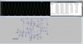
Here is the hybrid, now you have some sim fun.
More I can not do, ready for build some finetune decoule caps and such,, but maybe you can I have a lot of work with home and judge, because of a woodstove the judge is, but have already won.
As it is ready I go make a stack for working, I hope soon that trouble is over.
The hybrid is a all plate follower you need to use amplifier tube be mu = 20 x 2 -8 is output voltage (fet) open loop, a higher mu you need feedback who is current.
regards
Attachments
- Status
- Not open for further replies.
- Home
- Amplifiers
- Tubes / Valves
- Hybrid amp