Yes, one of secondaries has 180 degree capacitive coupling to the ground, so what? Stray inductance is minimal, so the driver requires lower output impedance for flatter frequency response. Nothing is absolute in electronics design; everything is optimisation.
Did you try trifilar phase splitters, compared to separate windings? I am following this with interest! ;-)
Did you try trifilar phase splitters, compared to separate windings? I am following this with interest! ;-)
Yes, years ago I have spent quite some time on input transformers / phase splitters (1:1+1); tried about every possible winding technique.
The point with trifilar windings is that the in-phase secondary is excellent in bandwidth (wich can be expected); the out-of-phase secondary however is very poor in bandwidth because the capacitive coupling is working against (can also be expected).
A lower source impedance certainly helps, but the two phases remain very unequal.
Separate windings on high permeability cores are the way to go, but this can also be done several ways.
I did not experience any poor bandwidth in phase splitting transformers. Stray inductance is very low, so higher capacitance to the ground does not matter for output symmetry; it loads the driver stage. Yes, for input transformers I prefer an electric shield between primary and secondary, because capacitances add some decrease in CMRR on higher frequencies, but it is the different story.
What is the point in transformer phase splitter, if not A2 drive? If A2 drive, the drives should be adequite, i.e. have pretty low output resistance that with input capacitance of the transformer forms a corner on pretty high frequency. 2 ducks by a single stone.
I go try or staple winding, so part primary, part secondary, primary, etc and between copper foil tape on ground.
or
first half primary part, a copper foil, bifilair secondary, foil, and the second primary part.
or
first primary part, foil, first secondary part, foil, second secondary part foil and secondary primary part.
read this book. Just do like jenssen and such prducers, she have good ones.
https://www.google.nl/url?sa=t&rct=...sg=AFQjCNG0-REPzGmaaxdjat9qTEzqHQk9Vw&cad=rja
or
first half primary part, a copper foil, bifilair secondary, foil, and the second primary part.
or
first primary part, foil, first secondary part, foil, second secondary part foil and secondary primary part.
read this book. Just do like jenssen and such prducers, she have good ones.
https://www.google.nl/url?sa=t&rct=...sg=AFQjCNG0-REPzGmaaxdjat9qTEzqHQk9Vw&cad=rja
I did not experience any poor bandwidth in phase splitting transformers. Stray inductance is very low, so higher capacitance to the ground does not matter for output symmetry; it loads the driver stage. Yes, for input transformers I prefer an electric shield between primary and secondary, because capacitances add some decrease in CMRR on higher frequencies, but it is the different story.
You do speak about transformer between tubes? these are different.
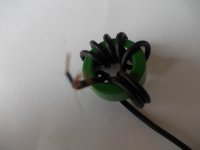
I did a gate transformer for smps supply (amp supply design) I did use a toroid 19 windings of small microphone wire did use the outside ground as a coil and the inside also, did get on 4.5 mH a leakage inductance of 122 nH. did read this somewhere and has tested it, that do fine.
Attachments
Last edited:
after some windings done with a drill machine, I get 2.30 henry, I go count the windings to see how much, but it looks like I get this with under 500 windings 0f 0.05 wire. Core transformer is nickel alloy.
PS I get this inductance with 261 windings, for 628 ohms I need 5 henry that is then 522 windings on 20 hz..
Now I need a bobbin fill calculator to get the wiring thickness.
PS I get this inductance with 261 windings, for 628 ohms I need 5 henry that is then 522 windings on 20 hz..
Now I need a bobbin fill calculator to get the wiring thickness.
Attachments


Last edited:
No Kees,
Inductance goes up squared when you double the amount of turns.
So when you need 5H, and you have 2,3H now with 261 turns, 385 turns will give 5H.
Inductance goes up squared when you double the amount of turns.
So when you need 5H, and you have 2,3H now with 261 turns, 385 turns will give 5H.
Ahh dank je wel Pieter.
Thanks, some learn again, never did now, but oke, I am not a transformer builder, this is quite new for me, special the line transformers, the upgoing square with turns do afcouse come really in play when have much turns, who i did not yet try, I can however calculate AL who is then 33763.5 nH or 33.76 mH then it do give outcome right, but is this not very high AL? is mine induction meter oke haha.
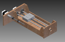
I wait for the copper band I ordered, for fighting capacitance, these do ruin the bandwidth, as I did read, this moment I do read about it, but I NEED to build a winder, I go use stepper motors, and some software. But I go wind the transformer, first a normal primairy and a two at one go secondary (bifilair) and measure things, because of this high AL it is nice to get low windings count.
Then when transformer do work can go on with amps.
regards
regards
Thanks, some learn again, never did now, but oke, I am not a transformer builder, this is quite new for me, special the line transformers, the upgoing square with turns do afcouse come really in play when have much turns, who i did not yet try, I can however calculate AL who is then 33763.5 nH or 33.76 mH then it do give outcome right, but is this not very high AL? is mine induction meter oke haha.
I wait for the copper band I ordered, for fighting capacitance, these do ruin the bandwidth, as I did read, this moment I do read about it, but I NEED to build a winder, I go use stepper motors, and some software. But I go wind the transformer, first a normal primairy and a two at one go secondary (bifilair) and measure things, because of this high AL it is nice to get low windings count.
Then when transformer do work can go on with amps.
regards
regards
Last edited:
That's real DIY 🙂
When you need some copper foil or magnet wire in a particular gauge, let me know; I guess the amounts are small.
When you need some copper foil or magnet wire in a particular gauge, let me know; I guess the amounts are small.
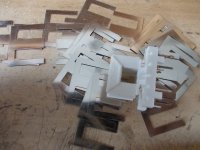
I have coil from a 220 volts relais and from wasmachine pumps, the copper foil I have ordered that version has glue so it sticks good, thanks for the offer.
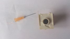
I have got the ide of using a needle for injection from the doctor, this can guide the wire very good, I need to remove the point because these is sharp.
the thin wire do fit very good, I remove all sharp edges so wire get not damaged. I did see winding machine nozzles but these are not available in small quantities, when you now please let now, I have ordered a arduino board and have wind machine software who I can change and play with and a lcd screen for setup.
regards
regards
Attachments
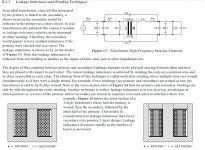
Part of a book how to get good transformer, or primary winded first, a faraday shield, then half the secondary, faraday shield, other half of secondary.
or half primary, then faraday shield, half secondary, faraday shield, other half secondary, faraday shield, and other half primary.
capacitance is then less.
or multi layering, 1/3 primary, half secondary, 2/3 primary, other half secondary, 3/3 primary, all separated with faraday shield. then most capacitances between the coils get canceled.
As wavebourn did say, when bifilair winding we get best balance, and low leakage and so a nice low ringing output with a square, but capacitance can do limit bandwith, I do not want use fiterling to correct, I try to get best windings technology and that do excist, however need a winder build for this.
regards
Attachments
Last edited:
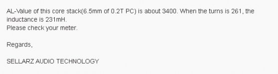
I have ask the seller about the al value of this nickel alloy transformer, he say this about it and that the inductance meter I have is not oke, because 261 windings is 231 mH and not 2.3 H, see the numbers it is devide by 10. the al value he says is about 3400, so what is wrong, are these cores so low in AL value because I read she are quite high.
Attachments
Last edited:
Seller has make mistake with one 0
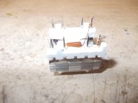
I have the stuff to make the transformer for the fase splitting. a small nickel permaloy core AL= 34000 and the copper folie for between the windings is also received.
regards
I have the stuff to make the transformer for the fase splitting. a small nickel permaloy core AL= 34000 and the copper folie for between the windings is also received.
regards
Attachments
Hi, everyone.
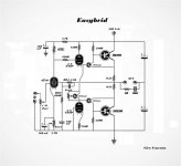
Here is my last project: I think it could be interesting in this discussion because it's very simple, cheap and solves some of the typical problems of the hybrid amps.
-Only one single power supply line.
-All stages DC connected.
-Imput pentode working as ultra linear RC stage by closing feedback ring on screen grid.
-Perfect control of output offset due to the DC connection of the screen grid on output.
-Bandwidth flat over 100 KHz
-Power output on 8 Ohm: 180 Watts rms (4 Ohm is not recommended).
No way for me to provide simulations,measurement of the distortion or other parameter because my lab is very poor (only signals generator and oscilloscope).
I finished the prototype yesterday now is playing and is working well.
Thanks for attention
Attachments
@Varaita: every so often i find designs that are clever and interesting in this forum. Your design is one of them. Thanks for sharing.
Here is my last project: <snip>
If I have time I do draw and sim it for you.
nice clever design, looks a little of mine who do now play here for several years. onbly these has only mosfets.
@Varaita: every so often i find designs that are clever and interesting in this forum. Your design is one of them. Thanks for sharing.
Thank you.
It's necessary to say that such an amp, in spite of the very simple circuit, requires some precaution:
-loudspeakers delayed connection system (automatic or manual).
-cooling system (when it works over 50 Watts).
If I have time I do draw and sim it for you.
nice clever design, looks a little of mine who do now play here for several years. onbly these has only mosfets.
Thank you.
It'would be great if you could find the time to simulate it and to have a spectrum analysis.
During simulation try eventually different value of resistor for the pentode plate and the series of triodes.
- Status
- Not open for further replies.
- Home
- Amplifiers
- Tubes / Valves
- Hybrid amp