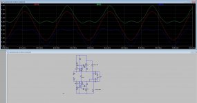
THis is not the hybrid, but the allfet, but place it here for info, little offtopic but I have here done a autobias with just one bjt, it keeps a minimal idle current very well, the diodes are used for this so it clipps when overdrive the amp, however have pretty high oneven harmonics, while even are -80dB or so.
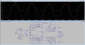
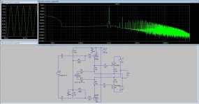
Green and Blue are 0.18 ohm source resistors and Red is output signal.
regards
Green and Blue are 0.18 ohm source resistors and Red is output signal.
regards
Attachments
Last edited:
For the hybrid attempts, I did see that I had per accident made a TEM 3200 amplifier like mosfet drivers. I did read there but I ask myself a 800 watts 300 amps motor module who is used in that TEM amp who is driven by a small tube who can never output enough current, that is why I did use a extra mosfet to drive the irfp250 types of mosfets, for 2sk1058 it do well drive it for max 2 each side because have low gate capacitances, so that man did something clever in that REM amp.
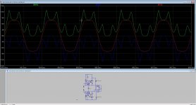
Oke, I go a other route, except the driver section I do keep that way, it do output -80 dB harmonics with 750mA idle, witghout feedback, no wrong it has local feedback because it are followers, but still nice.
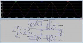
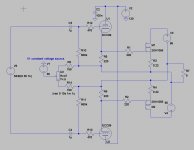
V1 is a constant voltage source, here I do adjust idle current, more negative voltage is more current however the output give both also higher voltage for 1.5 amp it is 56 volts on each side, who afcouse in bridge do cancel out to zero volts, I think the REM amp do the same, so carefull with touching case and speaker leads.
regards
Oke, I go a other route, except the driver section I do keep that way, it do output -80 dB harmonics with 750mA idle, witghout feedback, no wrong it has local feedback because it are followers, but still nice.
V1 is a constant voltage source, here I do adjust idle current, more negative voltage is more current however the output give both also higher voltage for 1.5 amp it is 56 volts on each side, who afcouse in bridge do cancel out to zero volts, I think the REM amp do the same, so carefull with touching case and speaker leads.
regards
Attachments
Last edited:
Kees
Direct DC coupled PP driver tubes to the OPS gates sonic wise are the best solution ,but the problem is that after certain time tubes will start to age , so small changes of driver tube parameters in function of time will cause big changes of DC offset and IQ of OPS , which is not good for the amp DC stability on the long time period .
Regards
Yers you are right, that is why mine amp in my home has a servo, this amp is also dc coupled, one tube as a CCS and one as a cathode follower.
I have this amp now already 6 years, without ever readjust it, yes the idle current get lower in time, that is why i also search and try a bias servo, a bias servo can also keep the amp biased and go never to class B but is difficult.
here it is, playing in my home and has a opamp servo circuit, keeps it withing 10 mV or less..
https://www.youtube.com/watch?v=-U-EFHi2epk
I do like the penthode input amp, on 10 mA it sings.
here with a triode on input.
https://www.youtube.com/watch?v=aFY4jhnNmXw
all is dc couipled to mosfets with a 6n6p.
regards
Last edited:
And this is a new one, has no chatodefollowers anymore but all plate amp, because I did hear tubes sound better in plate mode output, therefore I did use a beefy 6C19P driver and I but also other people did like the sound very much, also here a servo but not yet implemented, is test version. The sound is recorded with a mobile phone.
https://www.youtube.com/watch?v=mAYXzegWnn4
regards
https://www.youtube.com/watch?v=mAYXzegWnn4
regards
Kees
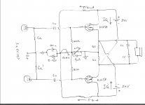
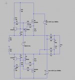
I like 6C19P tubes as drivers in anode follower mode driving one or more pairs of K1058 connected in Circlotron power bridge biased in A class , I think that for one pair of K1058 optimum B+/B+ is around 24VDC , for two pairs is around 35VDC and so on , any way I will try and go with AC coupled variant ,where 12V zener diode provide relative stable bias source , and yes , related to servo unit , advantage of Circlotron power bridge is that consist from same Lat-Fet devices ,K1058 ,which is not problem for precise matching , both device IQ will drift in the same manner in function of temperature ,output DC offset will be minimum , so single servo unit have to work in common mode for both OPS active device controlling only IQ`s ,
in my schematic that servo can be placed instead of NTC , but I think that NTC placed on main heat sink is just sufficient for relative stable OPS-IQ`s .
Attachments
And this is a new one, has no chatodefollowers anymore but all plate amp, because I did hear tubes sound better in plate mode output, therefore I did use a beefy 6C19P driver and I but also other people did like the sound very much, also here a servo but not yet implemented, is test version. The sound is recorded with a mobile phone.
https://www.youtube.com/watch?v=mAYXzegWnn4
regards
Very nice, I like it!
I like 6S19P tubes too! But they need helluva swing on grids to sing.
https://www.facebook.com/Wavebourn/videos/1380620975329533/
https://www.facebook.com/Wavebourn/videos/1380608128664151/
https://www.facebook.com/Wavebourn/videos/1380727271985570/
Last edited:
Very nice, I like it!
I like 6S19P tubes too! But they need helluva swing on grids to sing.
https://www.facebook.com/Wavebourn/videos/1380620975329533/
https://www.facebook.com/Wavebourn/videos/1380608128664151/
https://www.facebook.com/Wavebourn/videos/1380727271985570/
Thanks wavebourn.
For as it is a hybrid it do well, I can use it with or without feedback, but has complementairy output stage, no circlotron, when use these tubes as a ouput to a transformer then yes, you maybe need attention for the losses.
I have still gain with them, I did use them because need a low mu tube so I can also use feedback, it do work nicely all together.
Choise of gain tube is important for feedback or not, but I did test that with a high end listeing guy here and he did hear for shure the change, amp get more limited like sound with, so he did like it without.
The sound on youtube was with feedback because of the penthode used in input, the 6J51P I do like these a lot but are microphonic.
regards
The amps do sound well, I did hear well controlled for a tube amp who can also sound to warm, much of them do.
I like to be between warm and neutral.
Did you ever try 6AS7 tubes who are the same kind and also mu 2.5 with beefy output capacity, JJ makes them.
Only the heater needs more amp.s
I like to be between warm and neutral.
Did you ever try 6AS7 tubes who are the same kind and also mu 2.5 with beefy output capacity, JJ makes them.
Only the heater needs more amp.s
Here are nice transformers for self winding one.
Nickel Permalloy LE-25 Core and Bobbin for Transformer | eBay
But a little expensive so buy one complete and missing the fun winding.
Nickel Permalloy LE-25 Core and Bobbin for Transformer | eBay
But a little expensive so buy one complete and missing the fun winding.
Here are nice transformers for self winding one.
Nickel Permalloy LE-25 Core and Bobbin for Transformer | eBay
But a little expensive so buy one complete and missing the fun winding.
For line input?
Try toroidal current sensors. 2 of them with common shorted turn. You will be surprised. ;-)
10 times cheaper than this core only, but higher quality than you can wind on EI.
For line input?
Try toroidal current sensors. 2 of them with common shorted turn. You will be surprised. ;-)
10 times cheaper than this core only, but higher quality than you can wind on EI.
Well that is new for me thanks.
Can you give more info, because winding toroidal is not that easy, special when needed high inductance and impedance like 600 ohms
maybe a drawn oabout it, thanks in advance.
Last edited:
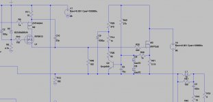
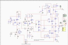
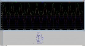
I have done some tests with auto bias runaway tracking, now I did chane some so it stays high impedance for tubes and still do auto bias with a single transistor what I did see on tubecad, I get 600 mA, and this get higher when drive harder with clip it is some more then 1 amp, maybe this is better then dropping, when I clip the amp it looks like idle current drops also. the small diode on the base do clip the signal so the bias stays on level.
For me, ? a autobias system is terrible difficult, to sense the dc component in the soruce resistor is very difficult, special for the circlotron, but maybe a clocked sample and hold and a pic do wonders.
regards
For me, ? a autobias system is terrible difficult, to sense the dc component in the soruce resistor is very difficult, special for the circlotron, but maybe a clocked sample and hold and a pic do wonders.
regards
Attachments
Last edited:
You need S/H instead of limiting bias, to avoid dynamic distortions caused by bias modulation by envelope.
http://www.cse.psu.edu/~kxc104/class/cse577/11s/lec/S07SampleHold.pdf
http://www.cse.psu.edu/~kxc104/class/cse577/11s/lec/S07SampleHold.pdf
You need S/H instead of limiting bias, to avoid dynamic distortions caused by bias modulation by envelope.
http://www.cse.psu.edu/~kxc104/class/cse577/11s/lec/S07SampleHold.pdf
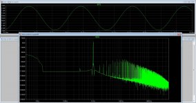
Yes I did mention this, because the dc compnent is what is needed, nice challence to make it, I have indeed more distortion when do the system with the bjt, special oneven ones but that can afcouse also result of balanced amp cancels even harmonics.
What concerns sample and hold circuit, it needs probe dc component in a 10 to 20 Khz audio signal so need a fast clocking..
Thanks for the PDF.
regards
No need for fast clocking, you can use integrating RC instead, like in your limiting regulator, but disconnect R when the output voltage goes above certain level, instead of limiting the voltage in the current feedback loop.
For line input?
Try toroidal current sensors. 2 of them with common shorted turn. You will be surprised. ;-)
10 times cheaper than this core only, but higher quality than you can wind on EI.
I did send mail but do not go to you, I do not now why.
here it is the answer there from me.
I do now when I put two low impedance 6 volt windings to each other I get 220v in and 220v out, I need a line input who do faseshift also and impedance 600 ohms or more. One winding on a current transformer do not be such high, the circlotron where it is needed for is a allfet version with fet input, make in unbalanced in the process.
regards
No need for fast clocking, you can use integrating RC instead, like in your limiting regulator, but disconnect R when the output voltage goes above certain level, instead of limiting the voltage in the current feedback loop.
I think I stick with a Vbe multiplier, that is quite more easy and do work fine also keep bias on a stable level. The autobias systems are not much used, and when used quite protected.
regards
- Status
- Not open for further replies.
- Home
- Amplifiers
- Tubes / Valves
- Hybrid amp