Hi Kees
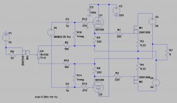
Be careful at +250VDC start up sequence since you can get fully turn on Q2&Q4 via C1 which can lead to instant huge output DC offset .
edit ,your OPS autobias solution look good .
That is not a problem, I have a woofer with 15 meters Xmax

Hi Kees
Be careful at +250VDC start up sequence since you can get fully turn on Q2&Q4 via C1 which can lead to instant huge output DC offset .
edit ,your OPS autobias solution look good .
Hi Banat
I can use a relais or a supply who heat tubes first and then set amp active, i have in mine a relais and dc protection because of the tubes are dc coupled to the amp wh works fine for over 6 years.
A relais who put capacitors to earth can also be done.
or these one who do not give trouble because both are indentical supply who give 0 volts.
Attachments

What if to use MOSFETs instead of diodes d3 and d6, with similar thermal characteristics like devices in output have?
What schematic do you mean? because these diodes do limit voltage for reference, these need not on a heatsink, because it is a servo.
regards
Hi Kees
If you made U9&U10(Ecc99)Cathode Followers than coupling caps(C2&C3)will be automatically on 0V potencial at amp start up ,they will slowly charging up, lower output impedance of CF as drivers is in advantage over those Anode Followers driving those CFP gates ,
what I don`t like is single GNFB taken from only one output phase , I suggest you to make that amp to be GNFB-free with reasonable good THD performance .
Regards
What schematic do you mean? because these diodes do limit voltage for reference, these need not on a heatsink, because it is a servo.
Sorry, it was not about the last diagram. ;-)
Hi Kees
If you made U9&U10(Ecc99)Cathode Followers than coupling caps(C2&C3)will be automatically on 0V potencial at amp start up ,they will slowly charging up, lower output impedance of CF as drivers is in advantage over those Anode Followers driving those CFP gates ,
what I don`t like is single GNFB taken from only one output phase , I suggest you to make that amp to be GNFB-free with reasonable good THD performance .
Regards
Yes this can be done however I do try not to use a cathode follower , it seems to sound better when use none, and without it feedback open loop to low.
I do afcouse question or a cathode follower do sound less oke, but the last amp I did make with a beefy plate follower a la 6C19 did very very wel.
Wat about the single feedback line, I can make it with symetrical supply and a symetrical tube drive set, hehehe I do more sim then build, better I combine things already excist, there is not much new about analog amplifers.
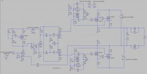
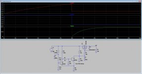
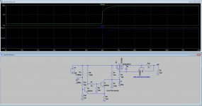
Here I have a dc coupled driver to the mosfets, that is a cathode follower, and some say that these sound thin.
second picture is a plate follower this one do not make trouble with offset as both capacitors get the same what cancels out, but still we need a protection for hybrids always and maybe even a dc servo and current servo.
Attachments
Last edited:
Sorry, it was not about the last diagram. ;-)
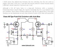
Oke, older schematics has diodes but are for gate protection, I have now test these auto idle current scheme with adjustments, it do work such that adjust to 800 mA it stays there in plus minus 20 mA from 0 to 100 Degree 0c that is nice, what it does when driven hard I do not now yet, this is a normal allfet circlotron who I did test already some months ago and a new one is underway (pcb making.).
regards
Last edited:
If your amp works out of class A I am afraid your servo would cause problems, unless you come with some S/H solution that remembers bias when driven above symmetric waveforms.
Hi Wavebourn
Thanks, I have after some reading and testing conluded you are right, a pity because it was a nice solution when working, I had a test on bench there with a irfp240 it did keep nice between 0.9 and 0.88 milliamps on a temp of from cold to bloody hot, a nice egg cooker.
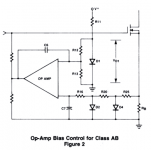
The amplifier TEM3200 has a bias tracking system, patented. I think a controller be used, however I have seen some who can maybe can be implemented, a opamp version maybe.
The transistor version I had have a low pass feedback to base, if audio stays away from that bese junction and only dc is present then it has to work without trouble except when overdrive it, a big cap to bring it back or maybe even a diode rectifier who clip it to value where it will not bother the asymetrical signals etc.
For the protection of the hybrid what Banat did mention, I do make a supply who do firts heat tubes and set wpuly on slowly with a delay, that make it safe, and afcouse a speaker protection relais.
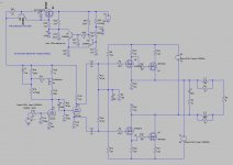
In picture is also a dc idle bias schematic did find that on the internet however that is for a complemantairy amp.
regards
Attachments
Have made a simple supply with a discrete schmit trigger and mosfet, it do have also a ramp up voltage, set it up for 60 seconds and then it switch on.
Second photo has also a short protection.
that way we have no trouble with things I hope.
regards
Second photo has also a short protection.
that way we have no trouble with things I hope.
regards
Attachments
Last edited:
If your amp works out of class A I am afraid your servo would cause problems, unless you come with some S/H solution that remembers bias when driven above symmetric waveforms.
Hi Wavebourn
I have seen some ideas on the internet, seems that use diodes who clips voltages when amp is out off class a, do cure that problem with unstable or missing tracking bias current, however autobias needs carefull tweaking, maybe just onces but still, the version with the single transistor can be adjusted with use of a diode over the sense resistor so voltages can be tracked for auto bias adjust, I think use of a schottky diode is a good idea because these have 0.3 volts so the autobias keeps better in track.
Maybe set the sense resistor on the drain and not on the output side will work even better, however making reference voltages and such is more difficult, just a idea..
Attachments
Last edited:
Have made a simple supply with a discrete schmit trigger and mosfet, it do have also a ramp up voltage, set it up for 60 seconds and then it switch on.
Second photo has also a short protection.
that way we have no trouble with things I hope.
regards
Not bad but what about to use tube(EZ80,6X5,...) full wave rectifier followed with simple CLC filter ?
Regards
Not bad but what about to use tube(EZ80,6X5,...) full wave rectifier followed with simple CLC filter ?
Regards
Yes that also works, and make a soft start, nice idea but we get much tubes on the hybrid, the regulator do the same, when switch on it ramps to 250 volts.
I do not now if rectifier tubes still are made.
regards
I use a 5u4g (5c3s or 5u3c) in my pre amp which is a readily available russian tube rectifier.
Just on the auto bias, the Pass lot are using optocouplers to bias their transistors. Is his something that could be adopted here?
Rectifiers are also from JJ who still make them, maybe it is a idea to do this, because then voltage comes on soft, but with the mosfet regulator I have also a very good ramping, and because it is a hybrid, to much tubes is not needed, but a rectifier tube included do look very professional and people who pay a lot for a amp do expect it is to gear.
Oke welcome Snax What concerns the autobias, I have thinking about using opto couplers for it, because that way I can isolate the servo completely, however sampling the source resistor is already difficult on a normally complementary amp and more difficult for a circlotron who has as for the allfet version has 2,3 volts on both outputs who result afcouse in 0 volts for the speaker, it cancels each other out, but for the opamp who is not part of the circlotron system itselfs and has a own supply it is difficult.
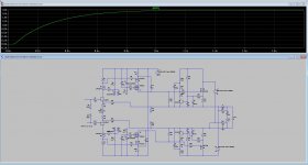
I have done a test for the allfet amp who is however not a hybrid and so this kind of test can not be done for the circlotron, but, I have also had the idea to use a dc coupled tube to mosfets version, and I think I can even do all tubes dc coupled when using a diff supply, and then use a bis servo, but as I did read everywhere a proper auto bias can best be done with a pic controller, and a sample and hold circuit.
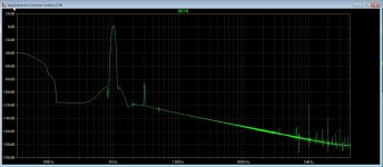
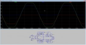
last photo is the dc coupled one, the first two is atuo bias allfet, normal and clipped, and as you see it stays biased, I did this by first bias it as a minimum with the drivers drain resistors, and then with autobias itselfs so now when run out of steam it has always a own bias adjustment, when get hot the autobias gets in. But I do not now if this works.
I do like however this system, a good designed one can flip distortion very low by keep it balanced also.
regards
Attachments

Hi Kees
What you think about replacing R8(150R) with some simple VBE multiplier attached to main heat sink and to get stable IQ thermal tracking ?
, btw, IMHO nothing is wrong with small tube rectifier to get +250V .
Regards
Hi Banat
I now I can use a Vbe but I like challenges, and i learn from it, that is why I am aktive on more thread's.
I have already working ones with Vbe or lateral mosfets, for the hybrid the 2sk1058 is the best choice and do not need a vbe, however a autyobias do regulate always independent of output lowering the distortion, special for circlotron important.
Bu first find out who try to hack me, I have continous attacks from different IP numbers and do not now how to remove, malwarebytes do not see it.
Attacks are every 5 minutes now even without firefox open.
regards
Attachments


Hi Kees
What you think about replacing R8(150R) with some simple VBE multiplier attached to main heat sink and to get stable IQ thermal tracking ?
, btw, IMHO nothing is wrong with small tube rectifier to get +250V .
Regards
The less nice thing is that only thermal tracking do not prevent the idle itself to be stable, with a bias automatic it do. But a circlotron is more difficult to make one. best is to sample not the output but just on supply, moving the source resistors to drain is then needed.
There are very good amps with a vbe tracking, it will do if idle current is set higher so class B stays away..
regards
regards
- Status
- This old topic is closed. If you want to reopen this topic, contact a moderator using the "Report Post" button.
- Home
- Amplifiers
- Tubes / Valves
- Hybrid amp