I use a gyrator now from your design, I hope you don't mind in stead of the mustage I did use, the gyrator has lower capacitance and give lower distortion I do like the distortion as it is with only first higher and the rest very low.
Your mustage is also a gyrator, just in mine that you borrowed I sacrificed PSRR in order to get lower capacitance. I use such a mustage-gyrator when current is higher.
You can use a voltage divider between them to make both tubes happy. I do that pretty often. The upper resistor of the divider shunt by a cap. Here is the example, a couple of 2M2 resistors.
Thank you, I did see that also on the internet couple days ago, you had a gyrator in your schematics some time ago I did use, is there a calculation for this somewhere? thanks.
kees
Your mustage is also a gyrator, just in mine that you borrowed I sacrificed PSRR in order to get lower capacitance. I use such a mustage-gyrator when current is higher.
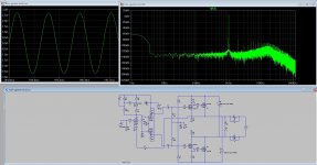
The gyrator as I did use see here, a test with feedback this time, the version as I did use has a cap for signal feedback and klow impedance the version now is high inpedance like you did use in a design, get quite low distortion with it when feedback and different setup.. the only problem is I can use just one output from circlotron for feedback it, but seems to work wel, but without a load !!
thanks for the help.
regards
Attachments

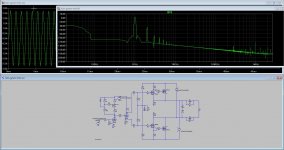
Do also fine with high frequenties like 50 Khz has -60 dB hd, and on 20 Khz has -70 dB here on picture is a version without feedback and fasesplitter.
I go use your advice in previous post but try to do thing dc coupled as much a possible.
regards
I go use your advice in previous post but try to do thing dc coupled as much a possible.
regards
Attachments
Hi Kees !
I follow this interesting topic and I think you are in the right track to design one very very good sounding amp ,
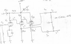
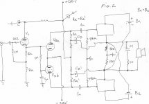
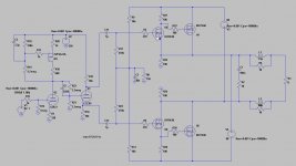
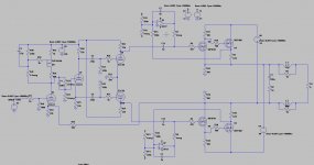
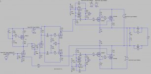
If you don`t mind here is my rough and basic ideas how that amp can be done , Fig1 represent modified Williamson front end driving Circlotron OPS ,and Fig2 represent modified Mullard front end driving Circlotron OPS , both schematics Do Not include any GNFB .
Best Regards
I follow this interesting topic and I think you are in the right track to design one very very good sounding amp ,
If you don`t mind here is my rough and basic ideas how that amp can be done , Fig1 represent modified Williamson front end driving Circlotron OPS ,and Fig2 represent modified Mullard front end driving Circlotron OPS , both schematics Do Not include any GNFB .
Best Regards
Attachments
Hi Kees !
I follow this interesting topic and I think you are in the right track to design one very very good sounding amp ,
If you don`t mind here is my rough and basic ideas how that amp can be done , Fig1 represent modified Williamson front end driving Circlotron OPS ,and Fig2 represent modified Mullard front end driving Circlotron OPS , both schematics Do Not include any GNFB .
Best Regards
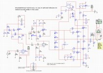
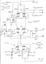
The best sounding amp I did is here, a dual mustage, but now a one gyrator one mu stage low output impedance as from Mr Wavebourn say it is. The amp has low feedback, and with use of a tube with MU is 20 it can be disconnected, the driver tube is a 6C19 high current tube who is normal for voltage regulating but did fine as driver for the mosfets.
The schematics you provide is known, the second one is the best why, because I try to avoid as much as possible the cathodefollowers, the versions I did try where with and without feedback, the feedback is current versions and very little to match MU of tubes.
Thanks for your idea,s
kees
Attachments
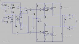
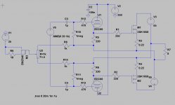
soem new tryouts done yesterday, it is changed om advise of Wavebourn because of tube did saturate or input tube has to low voltage.
The last picture is a williamson amp, with some modern stuff in it with feedback.
So I have to play a lot now, time to get the power end has two opamps for current runnaway protection, for this the wheel is also already invented but nieeds a extra supply for the opamps, a very small transfomer on the supply board wil do.
Attachments
Hi Kees !
I will follow your interesting topic further ,
BTW , I think you can also consider Atmasphere dual diff.cascoded VAS stage for you Circlotron hybrid project , bipolar B+and B- is around 300VDC , gain is around 24dB .
I will follow your interesting topic further ,
BTW , I think you can also consider Atmasphere dual diff.cascoded VAS stage for you Circlotron hybrid project , bipolar B+and B- is around 300VDC , gain is around 24dB .
Attachments
Hi Banat
This needs very high supply voltage, and have high impedance, that is why I did the old systems as the tube amps did in these old days, however I have this kind of system in the allfet circlotron. I have now set opamps in the circlotron who do make it stop runaway, it is only for the irfp series mosfets, for lateral it is not needed.
I have the current servo from tubecad and did a remake for this circlotron who has negative supply.
This I did build past year a dual mustage hybrid with only plate followers as I did hear it sounds much distressed as with cathode follower due to 100 procent feedback, it did sound very easy
and a high end guy did say it was indeed much better, I did use 6S19 tubes as driver to get enough current for mosfets.
@wavebourn however say this are also gyrators, except then for the first one, but is sounds very nice, amp has a dc servo because the 6S19 are dc coupled to the amp.
https://www.youtube.com/watch?v=mAYXzegWnn4
schematic in post #26 I did forget there the link.
https://www.youtube.com/watch?v=t_fngEFf53s
Here same schematic but now with a 6S51P penthode in triode mode, and afcouse the horn design from X.
regards.
Attachments
Last edited:
Interesting hybrid amp. How do you adjust bias, and how much do you use in the output mosfets? The opamps are only for dc offset adjustmet , right? Is this compound mosfet output stage better than the simpler lateral mosfets?
Interesting hybrid amp. How do you adjust bias, and how much do you use in the output mosfets? The opamps are only for dc offset adjustmet , right? Is this compound mosfet output stage better than the simpler lateral mosfets?
I test only right now, the opamps do make current protection for running out verticals, seems also to lower the offset as i did sim, but needs more adjustment and maybe diodes on mosfet inputs.
The compount mosfet has nice things like no more drop of voltages as seen with source followers because of gate source voltages, I use these also with laterals, there is no need for a servo then, but maybe let it in because do more then that.
How it sounds I do not now yet, are still busy with the allfet also.
regards
Well;
I don't think it is a good idea to power opamps such a way...
I have this from tubecad as a idea, so I do not now myself if this is good idea, I just try and add also diodes on the inputs, the opamp do regulate current it is set over the drain resistors to measure the current, seems to lower the offset also to some mV.
I have power the opamps with his own supply for as this is not clear, it can not through circlotron supply.
I have drawn yesterday also this kind of circlotron with tube driver, it is dc coupled, see picture. I had this type already 4 years back, do play now al that time in my home.
regards
Attachments
Last edited:
Well;
I don't think it is a good idea to power opamps such a way...
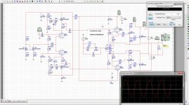
I have adjust the servo, so the opamp has not to much signal on it when drive amp with audio.
four diodes and two extra poles. the opamp do regulate current and offset, it do work and thermal runout is of the past if it do what it sims, need to see the low pass function and maybe adjust caps if bass is affected make RC time bigger.
Wavebourn, you as a tube expert, I have also here use the tips from you like the resistors and cap for lowering voltage on grid of second fase inverter, hope that it here also is the right way because this inverter is not the same as you advice first.
Attachments
Last edited:
Yes, 2.2 meg in your case (1.1 in parallel actually) probably is too much; I meant a Concertina with such values and high gm 6F12P tube. You can use 470k resistors. Also, the resistor between grids (1M) may cause some difference between voltages on grids due to grid currents. I would use lower it's value, like 470k.
Speaking of opamps, I would use separate power supplies for them referenced to outputs of the amp, or at least protected their inputs by diodes.
Edit: I see diodes; sorry I did not look carefully on the corrected diagram.
Speaking of opamps, I would use separate power supplies for them referenced to outputs of the amp, or at least protected their inputs by diodes.
Edit: I see diodes; sorry I did not look carefully on the corrected diagram.
Yes, 2.2 meg in your case (1.1 in parallel actually) probably is too much; I meant a Concertina with such values and high gm 6F12P tube. You can use 470k resistors. Also, the resistor between grids (1M) may cause some difference between voltages on grids due to grid currents. I would use lower it's value, like 470k.
Speaking of opamps, I would use separate power supplies for them referenced to outputs of the amp, or at least protected their inputs by diodes.
Edit: I see diodes; sorry I did not look carefully on the corrected diagram.
Oke thanks.
The opamps have own supply, can not be on circlotron supply.
It do work fine now, I have put diodes in it also, what I always do. it regulates the current very nice, and also the offset, keeps distortion also in a vast value, high or low idle current, but is sim.
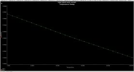
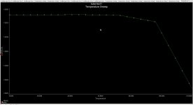
I have done a temp sweep in multisim, and it stays on place between 27 and 100 0c .
What concerns tube grid resistors, do lower them, and the 2.2meg I did such high to not load the amplifier, tubes like high impedance as you now yourself, that is why a mustage sounds so well the tube see many mega ohms because of it.
If I go use laterals in the circlotron then opamp is not needed, except then in a dc coupled tube mosfet version.
regards
regards
Attachments

I have decide to use this version and the version how fasesplitter do drive the mosfet without feedback.
I do think of the gyrator, is a mosfet mustage not better here, give voltage amplifier much more free swing who give more detail from music, or a gyrator with a source follower as I did in some other schematics giving low impedance and dynamic impedance for tube..
regards kees
I do think of the gyrator, is a mosfet mustage not better here, give voltage amplifier much more free swing who give more detail from music, or a gyrator with a source follower as I did in some other schematics giving low impedance and dynamic impedance for tube..
regards kees
Attachments
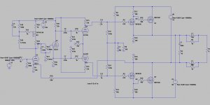
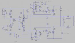
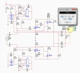
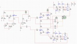
@Wavebourn what do you think about this one, I did use two gyrators who has low impedance and the distortion is on 100 watts output (simmed).
Maybe you see things because it somewhat strange design as I do every time as seems, there is not much to design again in amps world, everything is already tryed already.
The constant current mosfet on cathodes has to changed because 102 volts do give to much dissipation, but that is easy to do, or remove and use other idle scheme or automatic.
regards
Attachments
Last edited:
Afcouse the hyvrid needs a bias solution, I have done a autobias, on tubecad are different examples and I did use one who is also in a amp book.
Maybe some comment about it, because I can oversee things, thanks.
on the oicte you can see it stays very stable on idle current until 100 0c.
regards
Maybe some comment about it, because I can oversee things, thanks.
on the oicte you can see it stays very stable on idle current until 100 0c.
regards
Attachments
- Status
- Not open for further replies.
- Home
- Amplifiers
- Tubes / Valves
- Hybrid amp