Yes, that would be nice Quanghao, how much would it be? Also, do you still have another DAC board, for sale? If you could have aluminum color(not black) that would be nice too. This case is the last thing that I need, we need case to put everything together.
Alex
HI!
not I have price now. the front by aluminum 15mm .
Yes, i have one kit dac for you
please wait it!
thanks
quanghao
HI!
not I have price now. the front by aluminum 15mm .
Yes, i have one kit dac for you
please wait it!
thanks
quanghao
Great, ok, I will wait..
Quanghao, have you found anything about my pcb's? There is no sign of them here in Romania. Thank you.
Quanghao, have you found anything about my pcb's? There is no sign of them here in Romania. Thank you.
Hi!
it still go to you, please see: VNPost | Mã xác nh?n
Status: Accept sending (posting / collection)
Status: Accept sending (posting / collection)
Date: 15/03/2016 - 02:39:36
ZIP code: 100100
Attachments
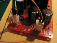
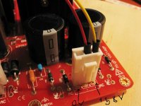
Quanghau can you tell me if I am connecting the transformer correctly:
In the pics purple/green = 12V, red/yellow = 158V.
My transformer gets very hot so there is a problem. In the pics above you are using a centre tapped transformer for the HV rail but only two diodes for half wave rectification?
In the pics purple/green = 12V, red/yellow = 158V.
My transformer gets very hot so there is a problem. In the pics above you are using a centre tapped transformer for the HV rail but only two diodes for half wave rectification?
Attachments

Quanghau can you tell me if I am connecting the transformer correctly:
In the pics purple/green = 12V, red/yellow = 158V.
My transformer gets very hot so there is a problem. In the pics above you are using a centre tapped transformer for the HV rail but only two diodes for half wave rectification?
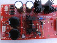
you wrong!
see my image
thanks
Attachments
Quanhao, on the schematic of the power supply, there is a C3A and C3B, with 47uf/450v, but there is no C3A and C3B on the BOM, but there is a C3, 100uf/450v. Can I use 100uf/450v here on C3A and C3B? Also on C1, 3.3uf/450v, can I use 2.2uf/630v instead?
Adeveza I have 2 x 150uf / 450V for C3A and C3B. Use anything 100uf or over with appropriate rating and diameter. 2.2uf would be fine for C1 I imagine.
I though about getting a 100uF+100uF 500Vdc F&T dual capacitor for the C3 position, apparently they are good. Mundorf do similar:
100uF+100uF 500Vdc F&T
I though about getting a 100uF+100uF 500Vdc F&T dual capacitor for the C3 position, apparently they are good. Mundorf do similar:
100uF+100uF 500Vdc F&T
Adeveza I have 2 x 150uf / 450V for C3A and C3B. Use anything 100uf or over with appropriate rating and diameter. 2.2uf would be fine for C1 I imagine.
I though about getting a 100uF+100uF 500Vdc F&T dual capacitor for the C3 position, apparently they are good. Mundorf do similar:
100uF+100uF 500Vdc F&T
Thanks passive420, I already have 2 x 100uf/450v and 2.2uf/400v wima cap, so I guess, I will use them. I will start building the ps this weekend, so we will see.
Just curious, which dac are you going to use these for? I was looking at the Buffalo, but boy, they are complex and expensive, but very flexible. I will use Quanghao's DAC.
I am having problems with the regulator board.
The 12V rail makes the transformer get very hot, I have tried with two different transformers and both heat up alarmingly quickly. All components and soldering are correct.
Also I cannot get over 158V DC output on the HV rail, VR1 does not seem to work. The LED lights up fine though.
Has anyone got their supply boards working?
Thanks passive420, I already have 2 x 100uf/450v and 2.2uf/400v wima cap, so I guess, I will use them. I will start building the ps this weekend, so we will see.
Just curious, which dac are you going to use these for? I was looking at the Buffalo, but boy, they are complex and expensive, but very flexible. I will use Quanghao's DAC.
I have the Buffalo II, still available but cheaper. I would also consider the Twisted Pear COD dac, good for the money. Quanghau's dac looks a real beast!
I am having problems with the regulator board.
The 12V rail makes the transformer get very hot, I have tried with two different transformers and both heat up alarmingly quickly. All components and soldering are correct.
Also I cannot get over 158V DC output on the HV rail, VR1 does not seem to work. The LED lights up fine though.
Has anyone got their supply boards working?
Do you have one trafo that do both hv and filament? if so, disconnect first the HV and trouble shoot the lv first. Isolate the HV and LV, trouble shoot individually.
I have the Buffalo II, still available but cheaper. I would also consider the Twisted Pear COD dac, good for the money. Quanghau's dac looks a real beast!
I just looked at their website, the Buffalo II is no longer available.
Do you have one trafo that do both hv and filament? if so, disconnect first the HV and trouble shoot the lv first. Isolate the HV and LV, trouble shoot individually.
Yes I tested both rails separately, the HV works in that it's converting AC to DC but I'm not getting the right voltage output. Not sure if VR1 should be adjusting current or voltage.
The filament rail was tested with two separate transformers and both got hot immediately, as did all four diodes.
I see the Buff II has indeed sold out sorry.
On the filament, I highly suspect there is something wrong with the build. Make sure diodes are installed correctly, and the regulator chip, which one are you using? There was something wrong with the board, I believe in one of the regulator chip. If the diodes gets hot right away, make sure also that they were not damaged, because of the initial error.
The way I do it is that I do it in steps, I would install the diodes first and fire it up to see if the install is right, then the regulator, and test again, until I get to the last part of the circuit. This way, you isolate the problem, if any.
You should use LT1764 as LT1084 has been implemented with the wrong pinout. I think this has been discussed a few times.
Yes I tested both rails separately, the HV works in that it's converting AC to DC but I'm not getting the right voltage output. Not sure if VR1 should be adjusting current or voltage.
The filament rail was tested with two separate transformers and both got hot immediately, as did all four diodes.
I see the Buff II has indeed sold out sorry.
I think VR1 should be adjusting voltage. What voltage are you getting?
JP - did you get your supply working ok? What transformer specs will you use?
If someone else can confirm the supply works ok then I know it's something on this board. No components overheated but it was the rapid rise in temp that was all wrong.
Diode look correctly oriented with Cathodes going to positive lead on capacitors and Anodes to negative.
If someone else can confirm the supply works ok then I know it's something on this board. No components overheated but it was the rapid rise in temp that was all wrong.
Diode look correctly oriented with Cathodes going to positive lead on capacitors and Anodes to negative.
I think VR1 should be adjusting voltage. What voltage are you getting?
I'm getting 245V DC at C3 filter caps. Output is 153V DC!
Somewhere the circuit is dropping 90V but the heatsink isn't even warm and VR1 simply does nothing. I'll probe around the reg and get some readings
I'm hoping you can get yours to work. That's something to go on.
Last edited:
- Status
- Not open for further replies.
- Home
- Group Buys
- HQ-IV tube output balance DAC