Thank you Quanghau.
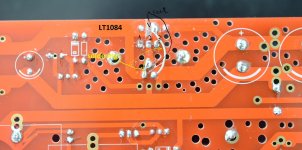
Are you sure the LT1084 is incorrect pins?
pin 1 = Adjust, pin 2 = Out, pin 3 = in
http://cds.linear.com/docs/en/datasheet/108345fh.pdf
Yes!
yes, I'm sorry about this,
please forgive me. I'm so sorry.
Hi guys,
I'm still trying to understand the circuit ;-). I'd like to use 12AU7 in the differential amplifier. If I do so with a B+ of 260V, assuming that I'm aiming for B+/2 (i.e. 130V) at the plate, if R1 and R2 are 47k, that gives me about 2.7mA. Does that sound right?
If I go for ECC99 in the cathode follower, and given that I have a B+ of 260V, how do I calculate R5, R14? Is it just B+/2 at the plate, and 10mA target, so e.g. R5 = ~13k?
The BOM specifies expensive tantalum resistors. I can't source those locally, and getting them from overseas looks like they're going to be $10+ each. I can get Vishay metal film locally for about $1. Is there that much difference in performance?
Cheers,
Jon
Hi jonwhitear!
yes, 12Au7 run at 2mA to 3mA, i see best sound at 120V to 150V.
I like this. ( for this tube input)
With ECC99 in put, you need run at 90V to 120V about 5ma , So R laod may be use 10K to 22K. Need down +B = 180-200V . No the tube in put I not like big current .
I Not like use metal film!
this have good sound and cheap: kiwame
KIWAME - 2 Watt Carbon Film Resistors
thanks
quanghao, I want to use ECC99 in the cathode follower, i.e. as "output" tubes. Do you mean that I need to reduce my B+ to 200V if I use ECC99 as output tubes? If so, that looks like I can't mix 12AU7 and ECC99, as they have different B+ requirements.
passive420, thanks - I'll keep an eye out for Koa parts as well, though it seems they're also difficult to source locally, and I recall Mouser's shipping to Australia is expensive.
passive420, thanks - I'll keep an eye out for Koa parts as well, though it seems they're also difficult to source locally, and I recall Mouser's shipping to Australia is expensive.
Hi jonwhitear!
the ouput i úe cathode follower no feedback. The sound nature
6dj8- ecc99 you can use 260V +B.
the sound very very detailed and vivid, the bass is love
thanks
the ouput i úe cathode follower no feedback. The sound nature
6dj8- ecc99 you can use 260V +B.
the sound very very detailed and vivid, the bass is love
thanks
Hi quanghao,
Is there an alternative for 2SK170/2SK117? I can't find either of those locally. Seems they may be obsolete.
Also, is there an alternative (or a different part number) for the UPC1237. I can't find that on Farnell/element14, Mouser or Digikey.
The PSU board seems to be laid out for an electrolytic at C5, but the BOM suggests a Wima (i.e. film). Is that OK?
The BOM specifies 100uF/450V for cap C3, whereas the schematic shows 47uF at C3A and C3B (i.e. 2 off) Which is correct?
There was mention earlier in the thread that C8, C9 should be 4700uF instead of 2200uF. There's plenty of space for larger caps, so what's the ideal value? The more capacitance the better?
There are a few options for diodes D3, D4, D8, D9 on the PSU board. Does it matter which one I use?
Cheers,
Jon
Hi jonwhitear!
Is there an alternative for 2SK170/2SK117? I can't find either of those locally. Seems they may be obsolete.
you can use other N- jfest ex: 2sk30....
Also, is there an alternative (or a different part number) for the UPC1237. I can't find that on Farnell/element14, Mouser or Digikey.
it is easy fine , ebay:
2pcs UPC1237HA UPC1237 C1237 1237 Integrated Circuit Protector IC SIP 8 New | eBay
The PSU board seems to be laid out for an electrolytic at C5, but the BOM suggests a Wima (i.e. film). Is that OK?
C5 can use 1 uf to 47uF min 100V. or not use if you conect GND heat to GND HV supply.
The BOM specifies 100uF/450V for cap C3, whereas the schematic shows 47uF at C3A and C3B (i.e. 2 off) Which is correct?
47uf min cap you can use for C3A, 3 B. all value is no problem.
There was mention earlier in the thread that C8, C9 should be 4700uF instead of 2200uF. There's plenty of space for larger caps, so what's the ideal value? The more capacitance the better?
you can use min 1000uf x 2, or one 2200uf to 4700 uf. all good, so the cap you have.
There are a few options for diodes D3, D4, D8, D9 on the PSU board. Does it matter which one I use?
D3, D4, D8, D9 the diode for HV, basic use 1n4007, you can use better diode.
any you want ask me more?
Jon I can send you a few 2sk170's for free if you don't mind the wait and PM your addy. Otherwise there are a few genuine sellers on ebay
Quanghau - Do C3 and C6 see the full plate B+ voltage?
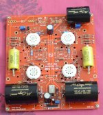
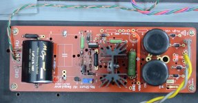
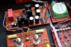
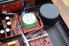
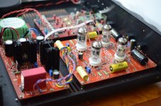
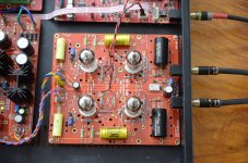
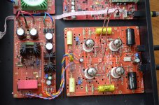
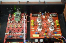
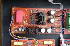
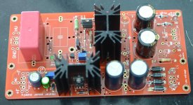
Some pics of my boards as far as they go for the moment. Waiting for shunt heat sinks and Russian polystyrene output caps. Have ordered balanced sets of JJ gold tubes - ECC802 & ECC88 to start with.
Went the distance and bought Vishay precision S-foil resistors for I/V, Takman metal film for signal and KOA speer carbons for plate and cathode resistors.
Quanghau - Do C3 and C6 see the full plate B+ voltage?
Some pics of my boards as far as they go for the moment. Waiting for shunt heat sinks and Russian polystyrene output caps. Have ordered balanced sets of JJ gold tubes - ECC802 & ECC88 to start with.
Went the distance and bought Vishay precision S-foil resistors for I/V, Takman metal film for signal and KOA speer carbons for plate and cathode resistors.
Attachments
[QUOTE=passive420
Quanghau - Do C3 and C6 see the full plate B+ voltage?
No. That is option convert balance to se .
Can use 0.1uf to 0.47 uf.
- ECC802 & ECC88 .
The paire tube I see the sound excellent .
Thanks
Quanghau - Do C3 and C6 see the full plate B+ voltage?
No. That is option convert balance to se .
Can use 0.1uf to 0.47 uf.
- ECC802 & ECC88 .
The paire tube I see the sound excellent .
Thanks
Dear quanghao,
I still haven't received the pcb's. Can you verify if there is something wrong. Tha tracking number returns no object in posta romana. Thanks. Victor
I still haven't received the pcb's. Can you verify if there is something wrong. Tha tracking number returns no object in posta romana. Thanks. Victor
any you want ask me more?
Thanks quanghao - that really helps. I'll be back to ask seem more questions when I next get stuck!
Jon I can send you a few 2sk170's for free if you don't mind the wait and PM your addy. Otherwise there are a few genuine sellers on ebay
<snip>
Went the distance and bought Vishay precision S-foil resistors for I/V, Takman metal film for signal and KOA speer carbons for plate and cathode resistors.
Thanks for the offer of the 2SK170s - PM on it's way.
Wow, those Vishay S series are pricey! I thought the audio note tantalums were expensive, but they're a different league! Thanks for sharing the photos. What are those bypass caps on the Mundorfs, and what have you used them?
Cheers,
Jon
Last edited:
Hi jonwhitear and all!
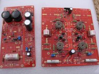
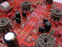
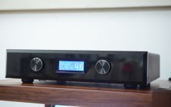
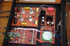
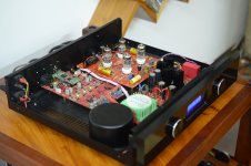
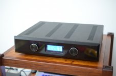
some image IV finis with DAC, please see it
thanks
some image IV finis with DAC, please see it
thanks
Attachments
-
 HQ-IV 10.jpg154.7 KB · Views: 167
 -
 HQ-IV 9.jpg315.8 KB · Views: 156
 -
 HQ-IV 8.jpg292.1 KB · Views: 151
 -
 HQ-IV 7.jpg267.9 KB · Views: 171
 -
 HQ-IV 6.jpg626.9 KB · Views: 174
 -
 HQ-IV 5.jpg330.6 KB · Views: 167
 -
 HQ-IV 4.jpg349.7 KB · Views: 181
 -
 HQ-IV 3.jpg316.5 KB · Views: 272
 -
 HQ-IV 2.jpg239.8 KB · Views: 288
 -
 HQ-IV 1.jpg296.3 KB · Views: 323
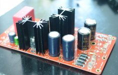
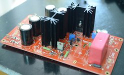
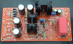
One wronng PCB LT1084 and fix
A small PCB with the LT1084 error, and this is the image to fix the PCB, and uses Lt1084
I am very sorry for you, and please do me!
A small PCB with the LT1084 error, and this is the image to fix the PCB, and uses Lt1084
I am very sorry for you, and please do me!
Attachments
Last edited:
Dear quanghao,
I still haven't received the pcb's. Can you verify if there is something wrong. Tha tracking number returns no object in posta romana. Thanks. Victor
Oh, it was too long. I think you've got it all
I will check it!
Thank you
Last edited:
Quanghao, I see you are using a different case on your finish pictures. Not the one you on the original DAC II. Do you sell or do you know where we can purchase that same case(chassis)?
Quanghao, I see you are using a different case on your finish pictures. Not the one you on the original DAC II. Do you sell or do you know where we can purchase that same case(chassis)?
Yes . Because tube big pcb and hot .
Ok if you like I can have chassis for this iv and dac 32 of me.
Thanks
Yes . Because tube big pcb and hot .
Ok if you like I can have chassis for this iv and dac 32 of me.
Thanks
Yes, that would be nice Quanghao, how much would it be? Also, do you still have another DAC board, for sale? If you could have aluminum color(not black) that would be nice too. This case is the last thing that I need, we need case to put everything together.
Alex
- Status
- Not open for further replies.
- Home
- Group Buys
- HQ-IV tube output balance DAC