Quanghao, I dont think these pcb's will fit in the original DAC II chassis. Do you or anybody have any suggestions as how they are going to build these kits? People who intend to use this tube output on the original DAC II?
Probably with Buffalo or Acko boards.Quanghao, I dont think these pcb's will fit in the original DAC II chassis. Do you or anybody have any suggestions as how they are going to build these kits? People who intend to use this tube output on the original DAC II?
Quanhao, clarification please, on the output main board, the value of the capacitor C1,C4 the BOM seems its 0.1uf/400v but the schematic seems its 1uf/400v, what was the intended value, please?
Quanhao, clarification please, on the output main board, the value of the capacitor C1,C4 the BOM seems its 0.1uf/400v but the schematic seems its 1uf/400v, what was the intended value, please?
you say about the supply??
you say about the supply??
No not the supply, the main board HQ-IV, on the BOM C1,C4 is 0.1uf/400v but the HQ-IV schematic, C1,C4 is 1uf/400v???
Not the Supply, C1,C4 on the HQ-IV main schematic.
No not the supply, the main board HQ-IV, on the BOM C1,C4 is 0.1uf/400v but the HQ-IV schematic, C1,C4 is 1uf/400v???
Not the Supply, C1,C4 on the HQ-IV main schematic.
that is for supply , near the load tube
you can use cap you have : 0.1uF to 10 uF. no problem!
thanks
that is for supply , near the load tube
you can use cap you have : 0.1uF to 10 uF. no problem!
thanks
Ok, thanks, one more question. The output cap C2,C5, you have 1uf/400v, will there be a big difference if I use a 0.47uf/630v instead. I have those on hand already.
Ok, thanks, one more question. The output cap C2,C5, you have 1uf/400v, will there be a big difference if I use a 0.47uf/630v instead. I have those on hand already.
Adeveza, this is the DC blocking cap. To customise the exact value to your system you need to know the input impedance of the next load in the system.
Coupling Capacitor Calculator by V-Cap.
Either have the blocking cap at the source or the amp, if you have one on your amps input, then you could leave the cap off the I/V board, less caps the better. When you build the I/V, check the DC on RCA output with and without C2,C5 cap.
I built my amp, I dont have a coupling input cap in there. I have a 100 ohm grid resister, and a 100k reference to ground. I could say I have 100k input impedance on my amp.
Adeveza, this is the DC blocking cap. To customise the exact value to your system you need to know the input impedance of the next load in the system.
Coupling Capacitor Calculator by V-Cap.
Either have the blocking cap at the source or the amp, if you have one on your amps input, then you could leave the cap off the I/V board, less caps the better. When you build the I/V, check the DC on RCA output with and without C2,C5 cap.
Thanks for that link BTW, it looks like I may have to use a 1uf to get the best response.
Thanks for that link BTW, it looks like I may have to use a 1uf to get the best response.
Note the filament use LT 1764 .
Can not use let 1084.
Thanks
Note the filament use LT 1764 .
Can not use let 1084.
Thanks
Yes, I got it, but just curious, why cant we use 1084? its cheaper too.
Also Quanghau - Why is C2 - 1uF not used on HV shunt?
Will a capacitor here be bad for the 2SK170?
Will a capacitor here be bad for the 2SK170?
OK Quanghau, I guess some things we will figure out ourselves.
I will use a cap for c2 as this will cause no harm and I will scope the output any way to see. On Your previous prototype 'green' pcb's this cap is in place an you say it works very well and now there is no rational reason to leave this huge area unpopulated. The board could have been smaller if this part is unnecessary.
Adevaeza - I too have both LT1084 and LT1764 ready but also considered using 1084 simply as I did not need the ultra low drop out, it can handle more current and as you say - it's cheaper.
There appears no reason not to use LT1084 unless we get a definitive explanation. The pins are correct for use and as long as you have one volt for the drop out then you should be good to go. 12VAC in will give you over 16VDC out which is plenty.
I also have a query regarding the H1 & H2 +70V jumper points on the HV supply board if anybody can figure them out.
Don't know why some parts are omitted in the HV PSU (I guess the 2SK170 did not live too long) and why LT1084 can not be used in the LV PSU. I received my boards only a few days ago and I am building the LV part to check if it works OK with NOS tube transformers with their standard 6.3V windings.
You will likely need LT1764 when using 6.3 V windings and 6.3V filaments. The fact that LT1084 is cheaper is eh...a non issue considering the total cost and the probable need when 6.3V windings are the only thing you have got. LT1084 won't cause an issue with 12V windings as far as I can tell but maybe Quanghau can elaborate ?!
Do you mean that the GND of the filaments is lifted by 70V ? Will check the board later when I am home again.
You will likely need LT1764 when using 6.3 V windings and 6.3V filaments. The fact that LT1084 is cheaper is eh...a non issue considering the total cost and the probable need when 6.3V windings are the only thing you have got. LT1084 won't cause an issue with 12V windings as far as I can tell but maybe Quanghau can elaborate ?!
I also have a query regarding the H1 & H2 +70V jumper points on the HV supply board if anybody can figure them out.
Do you mean that the GND of the filaments is lifted by 70V ? Will check the board later when I am home again.
Last edited:
Thank you JP. I wondered if it was a resistor divider on the B+ and if the heater GND terminal on the outer edge should be connected to star ground. These are to eliminate hum if any?
Also Quanghau - Why is C2 - 1uF not used on HV shunt?
Will a capacitor here be bad for the 2SK170?
YES! In PCB No. shunt
You not use C2 and C4, that is not good for the sound, and not good for 2sk170
thanks
OK Quanghau, I guess some things we will figure out ourselves.
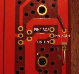
yes, with LT1084 , i found on wrong pin off it.
Change of the pin 3 and pin 2 as LT1084
im very very sorry, it is bad off me!
thanks
Thank you JP. I wondered if it was a resistor divider on the B+ and if the heater GND terminal on the outer edge should be connected to star ground. These are to eliminate hum if any?
no hum
1. you can connect GND of filament to GND of HV. it is no hum.
2. or you can connect GND filament to +70V, it is no hum.
all the sample , some tube may be you can use 2.
thanks
OK Quanghau, I guess some things we will figure out ourselves.
yes, with LT1084 , i found on wrong pin off it.
Change of the pin 3 and pin 2 as LT1084
im very very sorry, it is bad off me!
thanks
Thank you Quanghau.
Are you sure the LT1084 is incorrect pins?
pin 1 = Adjust, pin 2 = Out, pin 3 = in
http://cds.linear.com/docs/en/datasheet/108345fh.pdf
Attachments
- Status
- Not open for further replies.
- Home
- Group Buys
- HQ-IV tube output balance DAC