Yes. 6e5p triode wired should do it right? 20mA.10mA to the screen not in total !
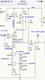
Cascaded XTP 01N100D top DN2540 bottom...use Mu-Follower output.
Thanks, Bas. I have that same UBT-1 fact sheet, but have forgotten about the reference to the 13w “enhanced mode EL509” amplifier.
Still following your journey with great interest! I have a bunch of 6e5ps in waiting too!
Still following your journey with great interest! I have a bunch of 6e5ps in waiting too!
Then again I might try an Aikido Cathode follower as well...I think I'll wait a while before drilling 🙂 I'm thinking of breadboarding it first. Usually I 'breadboard' in the amp itself. But here are too many uncertainties.
Aikido is great in a preamp, but in a power amp the noise is not your main concern. Here you need current. A mu follower with a pentode as follower can give you the current you need if you choose the appropriate tubes. Using a cathode follower is ok but then also use pentodes or 2 triodes in parallel. The problem with triodes is that they deliver less current with lower voltages (dynamics). Pentodes can still deliver even when the voltage drops, that’s why they do a better job as followers then triodes.
Imagine... the voltage on the grid of the follower goes up, so does the cathode (hence follower) but the power supply voltage doesn’t, so less voltage for the follower and therefore less current! But the screen grid voltage of the output tube also increases and more current will flow (but it’s not available) and here you have it....
Imagine... the voltage on the grid of the follower goes up, so does the cathode (hence follower) but the power supply voltage doesn’t, so less voltage for the follower and therefore less current! But the screen grid voltage of the output tube also increases and more current will flow (but it’s not available) and here you have it....
I've seen the late Tim's 859. And he uses a cathode follower. I'm not sure he would do it the same if he were to design it today.
For the historical record, he originally thought of using solid state for the driver etc, the 509s would have been the only tubes in the amplifier. I found that idea upsetting a the time, and I think he made the right choice, although I am sure the performance of the design could be "improved" with a little bit of ss.
Interesting. Thanks!For the historical record, he originally thought of using solid state for the driver etc
I think so too.I am sure the performance of the design could be "improved" with a little bit of ss.
Improvement can be made with tubes ... if it could be improved .
For now all I can see is the desire for improvement without somebody actually doing some measurements , calculations . Sticking a transistor is not necesary improvement . Like this all drivers for tubes could be made from silicon 😀
For now all I can see is the desire for improvement without somebody actually doing some measurements , calculations . Sticking a transistor is not necesary improvement . Like this all drivers for tubes could be made from silicon 😀
You can blame me for a vague question. I gathered that driving an EL509 in enhanced triode mode needed more attention than driving say an EL84. Hence my question...but ofcourse also interested in the advances made in mosfets..since Tim designed his amp.For now all I can see is the desire for improvement without somebody actually doing some measurements , calculations .
Plus asking how would YOU do it.
In essence I just wanted some food for thought. And as usual I'll build something the way I think is best...and listen....tweak...listen...ask questions...etc.
Then be my guest and start measuring, then you know first hand how to improve it. If you then found that 8.34mA is required, would you know what tube to use? I guess not. Tubes specifications are never exact and even between brands differ. Therefore use tubes that you know can deliver. Many cases the tubes needed you have lying arround or are not expensive at all. Only if you insist of using unobtainable tubes.
I have build amps using 18 tubes because i could improve linearity and it cost me nothing at all.
I have build amps using 18 tubes because i could improve linearity and it cost me nothing at all.
Attachments


Hi Bas,
Any further development in your effort to build the UBT-1 “enhanced mode” EL509 amp?
As Bas mentioned elsewhere in this thread, the UBT-1 fact sheet has the following:
“A 13 watt amplifier has been successfully built using a 6KG6/EL509 running 270 volts on the plate, running at 150 ma, in “enhanced-triode” mode”.
My question - has anyone seen this build and could you provide the schematic?
I'm thinking of using "Rod Coleman Shunt Cascode - Power Tube Driver" Rod Coleman Shunt Cascode - Power Tube Driver with the 6e5p. Even though a simple 6e5p with ccs and using the mu output would likely suffice.
I recall using 12B4A as cathode followers in the first version of my G2-driven PL519 SE amp fifteen years ago. Worked fine as far as I can remember, but the next version used Mosfet followers. 6E5P should be an excellent choice due to it´s high gm, I´ve used it sucessfully to push some smallish output tubes into class A2.
Good to hear!6E5P should be an excellent choice due to it´s high gm, I´ve used it sucessfully to push some smallish output tubes into class A2.
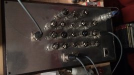
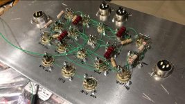
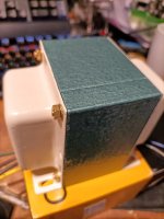
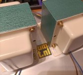
Prepping the ubt-1. They may be good.. But they are supplied pretty rough looking. Replacing the iron bolts with brass. Wrapping them in paper..


Bas, looking real good! But do you know what you are building yet? 😀
You mentioned B+ adequate to put 270 Vdc between cathode and plates, and UBT-1 with 1.6k primary. What are the other operating point and drive parameters?
I’m eagerly waiting for your to show the way 😉
You mentioned B+ adequate to put 270 Vdc between cathode and plates, and UBT-1 with 1.6k primary. What are the other operating point and drive parameters?
I’m eagerly waiting for your to show the way 😉
- Home
- Amplifiers
- Tubes / Valves
- How would you drive an EL509 in enhanced triode mode.