well,one can do everything with already grown some brain and some cojones
but, as I said, we need to take care about those new ones, having brain too small and cojones too big
so, just let continue to impose some rules to them, we can all later laugh at any stupidity which is hurting just pride

but, as I said, we need to take care about those new ones, having brain too small and cojones too big
so, just let continue to impose some rules to them, we can all later laugh at any stupidity which is hurting just pride

Giovanni,
Please have a look at this thread, where a member had created a short turn and experienced heating, even with a aluminum (non-magnetic) clamping bar:
https://www.diyaudio.com/community/threads/toroid-mounting-getting-hot.96235/
Please have a look at this thread, where a member had created a short turn and experienced heating, even with a aluminum (non-magnetic) clamping bar:
https://www.diyaudio.com/community/threads/toroid-mounting-getting-hot.96235/
Guys I sure trust all of you and it couldn't be any different, were we discussing about, say, photography, sailing, cooking (...) where I have some personal experience I could state something off of my own baggage but this is not the case and let me ask you something, were you in my position, with no experience, would you attempt some of the things you are suggesting me? Let me tell you something more, the guy who applied the soft start and bar between the transformers is a microwave tech working in the filed since over 30 years and been working for TV stations (and not just those) all across the country, if not because I am a total ignorant and have no experience don't you think I should trust him being the one in charge and, maybe, after having finally biased the amp, maybe maybe, submit your objections to him?
Of course i care about it all being safe, I have some doubts that the rest of my audio gear is "safe" with regards to grounding (Sansui AU-D7 from the 80s recently restored, Adcom GFA535 and GFP235 recently upgraded and restored, Carver TFM-6C, Sony 505ES, Girodec...) and I am almost as sure that the people who engineered that stuff knew something more than I do about it...
Hopefully I will borrow the DMM today and in the afternoon, after wearing my thick running shoes and making some anti superstition rituals I can give it a try with P1 and P2
Grazie
Last edited:
Hi Giovanni,
it is very easy to modify your F4 so that it is safe.
1. You only have to make an electrically conductive connection from the safety ground of the IEC Inlet to the housing.
Can you handle a soldering iron or do you know someone who can? This is done in 5 minutes.
2. You can easily replace the aluminum bar with a hardwood strip. Simply get a halfway suitable strip from the hardware store, e.g. made of beech wood, remove the aluminum rod (I wouldn't loosen the electrical connections on the terminal block, just leave them on and push the block a little to the side so that you can remove the AL bar) and than use it as a template to cut length and drill holes in hardwood strip.
Not beautiful but functional
Then we and you can sleep in peace, no one complains around here anymore and you can relax and adjust your amplifier correctly.
Good luck and have fun with your amplifiers!
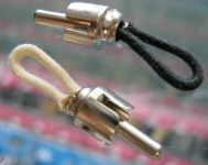
that aluminum bar which is making short winding for both transformers is (most likely) doing nothing else than forcing them to work very hard, resulting in heat and hum
(maybe they're in antiphase, easing things, but better to not count on that)
so, before proceeding with anything , you need to understand that you have same situation as having a car standing in place, gear in neutral, with engine on max RPM
maybe we didn't stress it enough for your level of understanding, but this is extremely important , same as lack of safety GND connected to case
your guy is maybe expert in some other fields, but it seems he's not having enough experience in this exact area of expertise; simply, his day job is of other expertise
Since there are many experience readers on this thread, I want to ask the question what is the correct way of fusing in Giovanni's case?
For example, it looks like the power plugs used in Italy are 180 degree rotationally symmetric and one cannot tell if a particular side has been plugged into Live or Neutral. Is this one of those cases where one really internally needs to fuse both sides?
Also I cannot tell if each transformer is fused indivdually.
in Italy is same as my neck of wood - non orientated 230Vac wall inlets, 99% (all modern ones) having safety GND connection
practically Schuko, embraced old German standard
so, even if logic is dictating that each wire have dedicated fuse, praxis is that majority of gadgets are fused in just one line
anyhow, that detail being relaxed with fact that safety gnd is mandatory, with exception of so called "double insulated" ones
and yes, when having dual mono construction, meaning each channel having own Donut, it is logical and proper that each Donut is having own fuse ( and NTC/soft start)
anyway, we can chat until our Sun nears Red Dwarf phase, and question is will Giovanni conduct necessary changes
maybe some of other 'Talian Boyz can chime in, and stress in their language how serious we are, regarding few important details
post #87, and counting......
Buongiorno everybody,
I know very well the importance to have a GND connection on electrical appliances, as a teen when I was playing with ham radio I remember a particular RTX a friend gave me to listen with (back in time I could not go TX on HF bands), still remember the radio, a Yaesu FT101, back in time (late '80s) houses didn't have a GND, at least I don't remember my parents to have it, every once in a while I play with the Yaesu I would get quite some chill down my spine...
I live on a small island where until 5-6 years ago we used to produce our own electricity with Diesel engines which, until like 20 years ago or little more, where off of submarines, I once saw a piston which was larger than a bar table; nowadays we finally get the AC off the mainland but distribution is still through mostly aerial cables and on contrary of what happens on the mainland with don't have a phase-neutral line but a phase-phase and in fact when we need to work onto house energy distribution we have to carefully pick the right differential switches not to end protecting just one leg of the layout.
Of course when my apartment was (partially) refitted we added a ground pole, now this is not my job, I can and did switch old mono wire cables with new ones and also updated the differentials panel but, again, did it along with a supposed-to-be-professional and then replicated what he did when I had to continue the refit myself, have no clue if and to which point it might matter with the above issue but this is how it is.
In a couple hours I will repeat the safety procedures, including some superstitious ritual, and try to adjust the two trimmers, the amp will anyway have to go through the cures of a tech and I will then ask him about grounding, I am curious to know why both the one who built it and the one who repaired it (the blowing fuse due to sudden high load on the caps, oh, two fuses of course!) didn't put chassis to ground (unless it is and I can't figure it out).
Working on one channel, P2 is very sensitive, a small adjustment brings quite a change, P1 seems less sensitive, I lowered DC output and raised bias to almost 130, letting it warm up and repeat

On the other channel I got offset at about 0.1 but bias won't go any further than 70mV with P1 all the way clockwise
I assume you tried turning P1 on the second channel counterclockwise and the bias only drops? If this is the case then you will need to make some measurements and likely then resistor changes.
Edit: What about the first channel? Were you able to increase the bias closer to 200mV across the source resistors?
Edit: What about the first channel? Were you able to increase the bias closer to 200mV across the source resistors?
The pot only does almost one turn and the range is from a few mV up to about 70mV, what might that be?
I raised the bias a little but it won't go past 182mV while trimming down DC to around 0 🙄 the pots by the way only allow about one turn, my guess is the thing has to be dismantled and checked values but too strange the other channel doesn't raise past 70mV and in fact, finally, the almost working channel is finally getting warm which has never happened before.I assume you tried turning P1 on the second channel counterclockwise and the bias only drops? If this is the case then you will need to make some measurements and likely then resistor changes.
Edit: What about the first channel? Were you able to increase the bias closer to 200mV across the source resistors?
Working channel is slowly raising from about 180mV to past 190mV.
Switched it all off, measuring along the six mosfets on the working channel the voltage was from 190 to past 200, this thing definitely not just a matter of trimming up and down.
Last edited:
Please check (visually) for both channels resistor values for R8 and R9. For each channel, try measuring the voltage with one probe on the Gate (left) pin of one of the mosfets on the N side and the other probe on the Gate (left) pin of a mosfet on the P side. We want to verify the TL431 setup is correct. It seems like you are not getting enough voltage from it and quite likely you will need to change out R8 to something higher.
As for why one side only goes to 70mV, that has to do with variation in the Vgs voltages of the mosfets. (So for a given voltage, one mosfet might turn on harder than another.)
As for why one side only goes to 70mV, that has to do with variation in the Vgs voltages of the mosfets. (So for a given voltage, one mosfet might turn on harder than another.)

Let me give a resume, first and foremost I shortened the inputs with an RCA cable, then measured the offset on the apparently working channel with the two probes connected to the speakers output, on the positive I put the probe of the second DMM and the other probe on either the P leg of the mosfet or by the pinhole right above the R17-18-19... resistor, tuned P2 to get the closest to 0 for DC offset and then slowly raised P1 to bring bias from 120mV to 175mV after which bias started to raise quickly and could definitely feel heat raising too. P2 needed a very slight adjustment as it increased a bit.
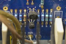
these are R8 and R9

here I can tell something is wrong with Q11, a leg is not soldered even tho I think it still does an electrical contact
these are R8 and R9
here I can tell something is wrong with Q11, a leg is not soldered even tho I think it still does an electrical contact
Attachments
So if a channel doesn't get enough bias what does it depend on, the mosfets not being matched? Could they have such a swing, I mean, I bought them all on the DIY audio store, one channel measured 120mV before biasing and the other 70mV?from the build guide...
Just asking to understand, grazie
Just a normal quirk of the F4 amplifier. Lots of people find that R8/R9 needs a bit of a value change to reach the bias level we want and need to get to. My own F4 has a 5K resistor at R9.
Last edited:
Even perfectly matched triplets can have this problem. It really depends on the Vgs of the particular parts. There's a range and some just needs more voltage to get at the desired current level.
If my eyes didn't fool me you have 22.1K for R8. Notice that in the last published schematics in the F4 manual, that value is 27.4K which allows for more adjustment room for increasing the bias.
If my eyes didn't fool me you have 22.1K for R8. Notice that in the last published schematics in the F4 manual, that value is 27.4K which allows for more adjustment room for increasing the bias.
- Home
- Amplifiers
- Pass Labs
- How to turn a dual mono F4 into a mono block?