@Dennis Hui @william2001 Ciao William, ciao Dennis, buonasera a tutti, got it about the mosfet, at the end of the day I got impressed by numbers on the multimeter, seemed too much of a difference between 120mV to 70mV. Learnt one more thing about "shorting" the inputs, I would need an RCA to short, dunno if I made some damage by shorting the two channels, I will add a note about this.
Also thank you for noticing the R8 value, once we tear the mosfet boards apart we'll swap accordingly and also check what looks like a missing welding on Q11 and give it all another check.
Just spoke with the guy in charge (he is also in charge of putting together the BA-3 preamp), within this week I will take the amp to him and we will spend some time together as to ease his work by explaining what I learnt thanks to all of you guys about how to set the amp.
By the way, I am still very glad that you gave me the boost to at least try and take measures and that I could finally at least feel the A Class warmth
I have a couple days to add further notes, if you have any it would be really appreciated.
Grazie a tutti
p.s. oh, one more thing that I learnt is the offset, kinda difficult for me to put it into English words, an oscilloscope would be self explanatory but I got what it is meant for and why to aim reaching 0 on the meter 👍
It is nice to have money, plug and play but so much nicer to know why once you plug it can also play...
Last edited:
Just thought of something: Please make sure that P1 is dialed all the way back down to the zero bias position before powering up after changing R8 or R9. This is to avoid the potential for a very large current at start up.
In fact, it might be a good idea to adjust P1 while the amp is powered on to verify this has been done properly, before changing R8 or R9.
In fact, it might be a good idea to adjust P1 while the amp is powered on to verify this has been done properly, before changing R8 or R9.

@Dennis Hui Buongiorno Dennis, excellent advise, grazie mille, I will put it on the notes I am arranging among which R8 (from 22.1K to 27.4K) on both channels and R9 (try with either a 6.xK or 5K) on the left channel (where bias doesn't get past 70mV) and, eventually, to have a pid added on top of one of the big resistors below the mosfets as to put a probe to easily check the bias current.
I'd trim P1 counterclockwise right now, I know I can do it regardless of the amp being switched on or off, to be honest I am little afraid to switch it on because when I did my last attempt the temperature started to raise quite quickly and I wonder if some damage happened as I got the "shorten" input wrong as I did a shortcut between both channels rather than shorting just one channel.
Grazie ancora
I don't think you've hurt anything with your input ground error. I wouldn't worry about that.
Something else I would mention, and I think ZM brought this up too.... We normally recommend a large round washer to secure the power MOSFETs to the heatsink on these projects. Gives a more even pressure on the part. Look at my picture at post #25 for an example.
Something else I would mention, and I think ZM brought this up too.... We normally recommend a large round washer to secure the power MOSFETs to the heatsink on these projects. Gives a more even pressure on the part. Look at my picture at post #25 for an example.
@william2001 Grazie William, added another point to my note, will look for washers.
Found a broken RCA, should I short it and try again to switch on and check what happens with bias on the channel where I have swing between 100 and 120mV among the FETs?
Found a broken RCA, should I short it and try again to switch on and check what happens with bias on the channel where I have swing between 100 and 120mV among the FETs?
Giovanni, I would either increase R8 or decrease R9, but not both. With both you may run into the opposite problem that the lowest bias achievable may be too high.I will put it on the notes I am arranging among which R8 (from 22.1K to 27.4K) on both channels and R9 (try with either a 6.xK or 5K) on the left channel
Dennis I thought that my BOM was not updated and that's why "If my eyes didn't fool me you have 22.1K for R8. Notice that in the last published schematics in the F4 manual, that value is 27.4K which allows for more adjustment room for increasing the bias."
So would you suggest to leave the right/working channel as it is and then on the other one change R8 as per above or to do the same surgery on both channels and then, eventually try and also swap R9?
So would you suggest to leave the right/working channel as it is and then on the other one change R8 as per above or to do the same surgery on both channels and then, eventually try and also swap R9?
Your "working" channel is still too low. Change R8 to 27.4K on both channels and let's see where you are at after readjustment.
Agreed with William. Just perform the R8 27.4K change on both sides and see; you most likely will be fine.
Note that for both channels the mosfets are already turning on (you're seeing significant bias current) so you likely will need just a bit more adjustment room.
Note that for both channels the mosfets are already turning on (you're seeing significant bias current) so you likely will need just a bit more adjustment room.
Ok, I will add this to the note and yes, I will turn P1 counterclockwise anyways, do you suggest I do it with the amp off or better turn it on, turn the pot down and check?Your "working" channel is still too low. Change R8 to 27.4K on both channels and let's see where you are at after readjustment.
Either one. Raising R8, or lowering R9 is going to wake this thing up so we don't want any surprises on power up after the component change. We just want to start with the bias low and bring it up gradually, slowly, and in a controlled manner. We will "sneak up" on our final setting.
Good morning everybody, yesterday I switched it on again, shorted the RCA on the working channel, measured bias and turned P1 all the way down, same thing on the other channel, now about to pack and hope my guy has a spot for me to carry it over (here it is all about walking and he lives up by one of the hills...).
Buongiorno @JSA1971 my friend Joe gave me green light to get him the amp last Saturday so I will have to wait a little to hear from him, I am confident that by following yours all suggestions it will get up to work properly and, hopefully, to drive the big white JBL woofers.
In the attached notes I put on top the R8 swap from 22.1K to 27.4K and, eventually then swap R9 from 10K to somewhere in the 5K range to allow more flow towards the mosfets, I still don't understand how a channel raises to almost 200mV once warm while the other doesn't get past 70-80mV, somebody wrote it being normal during the F4 building process, I just hope nothing is broken but the project seems quite simple once my friend illustrated me off the schematics, it will probably be a pain to disassemble the chassis to work on the boards but not much to play with once teared apart.
Grazie for your concern
Giovanni,
If changing R8 from 22.1K to 27.4K allows the amp to be biased properly then just leave it as is and DO NOT lower R9.
If you can already bias with R8 at 27.4K and then you lower R9 from 10K to 5K, there is a very good chance you will end up damaging the mosfets because with P1 = 5K, the minimum voltage for setting the bias with R9 = 5K is the maximum achievable with R9 = 10K.
Again, please tell your friend that if you can bias properly (by that I mean you can get at least 0.2V across the 0.47 ohm source resistors) then do not change R9.
Ciao @Dennis Hui yes, I put R8 on top of the list and then, eventually, swap R9 too and following the advise of another forum member, before taking the amp to service, I turned P1 all the way down (and measured it actually did) to avoid frying the mosfets
Grazie
Grazie
I'm making the assumption that there is a language barrier issue going on here. What several have pointed out is that either change R8 or change R9 but not both. If you have to change both, something is wrong with the circuit.
To beat a dead horse, replace R8 as planned. Attempt to bias. If it does not bias properly then the work to date needs to be re-reviewed and troubleshooting procedures need to be implemented.
To beat a dead horse, replace R8 as planned. Attempt to bias. If it does not bias properly then the work to date needs to be re-reviewed and troubleshooting procedures need to be implemented.
There sure is a language barrier made pretty obvious by the flag in my profile @6sX7, I told him to replace R8 and, if that alone doesn't make it, then R9, not both to begin with.
I am 100% sure he will get to fix the issue, he is very skilled and does that with a passion, the circuitry is not uber complicated, too bad I missed the warmth during these really cold past months...
I am 100% sure he will get to fix the issue, he is very skilled and does that with a passion, the circuitry is not uber complicated, too bad I missed the warmth during these really cold past months...
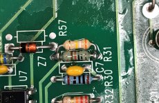
I'm a little lazy and impatient sometimes. If that was mine I would just piggyback another 10k resistor onto R9, which gives you 5k total there. Way faster and easier than a bunch of teardown and disassembly.... In fact I did that on something at work today to lower the value... see R31 on this picture. If there was another resistor in the way, the piggyback could go straight on top.
Attachments
- Home
- Amplifiers
- Pass Labs
- How to turn a dual mono F4 into a mono block?