I think I've found an easier option to work with from the hardware side. ADC128D818
for A/D conversion and PCF8574A to take care of digital I/O should cover everything. Are these compatible to write software for?
http://www.mouser.com/ds/2/405/adc128d818-439003.pdf
http://www.mouser.com/ds/2/405/pcf8574a-555743.pdf
for A/D conversion and PCF8574A to take care of digital I/O should cover everything. Are these compatible to write software for?
http://www.mouser.com/ds/2/405/adc128d818-439003.pdf
http://www.mouser.com/ds/2/405/pcf8574a-555743.pdf
I think I've found an easier option to work with from the hardware side. ADC128D818
for A/D conversion and PCF8574A to take care of digital I/O should cover everything. Are these compatible to write software for?
http://www.mouser.com/ds/2/405/adc128d818-439003.pdf
http://www.mouser.com/ds/2/405/pcf8574a-555743.pdf
I bought some PCF8574s sometime back, I'm sure I was going to do something with them. When you can find them in a databook from 1987, and they are still here, they are very popular. I see the ADC128D818 has integrated temp sensor, nice. Short answer, yes.
MI
I used PCF8574As in the Pitchfork Preamp controls, so I'm familiar with them. I know they are on a hi state on power up so quick turn off code is needed. I've got DC protection designed. I may need to add a pull-up resistor to P7 yet. I need time to read the data sheet again.
Attachments
As usual I'm late to this party. This is a perfect solution for what I want to do, plus way more. But I could adapt it. Any PCB group buy in the plans, or did I miss a post somewhere?I used PCF8574As in the Pitchfork Preamp controls, so I'm familiar with them. I know they are on a hi state on power up so quick turn off code is needed. I've got DC protection designed. I may need to add a pull-up resistor to P7 yet. I need time to read the data sheet again.
Rick
It's still in the design stage. If there's enough interest a group buy is possible. Gerbers will be available.
Thanks for the update j. I'll be following this thread with interest.It's still in the design stage. If there's enough interest a group buy is possible. Gerbers will be available.
To run dual DC protection circuits, would it be better to combine the input signals to the Arduino and connect on one interrupt pin, or add another interrupt pin in software?
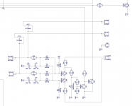
In fact, to add a channel (or multiple channels) you can just duplicate R26, C12, C13, D13, D21 as many times as needed and connect the right sides of D13, D21 in parallel, as it's done with 2 channels already here. Is that what you're looking for?
Arduino supports 2 hardware interrupt channels and both of them are already engaged with DC offset and over-current sensors.
Arduino supports 2 hardware interrupt channels and both of them are already engaged with DC offset and over-current sensors.
Attachments
I have 2 complete standalone DC detection circuits. One on each binding post of the amp. Their signal output pulls the line low in normal operation, and lets it go high on fault. I'm bringing the signal from each to the control board separately. Being they pull the line low for normal operation, they can't be paralleled together, or the signal wouldn't go high unless both were in fault. I'm trying to reuse your code as much as possible, but I've noticed you used two hardware interrupts already. I've been reading that software interrupts can be slow to react, and I'm still pretty terrible at coding. I can combine the signals with a dual optocoupler (creating an inverting buffer) and modify the code to require a high signal. I'm just wondering if that would operate better.
Last edited:
I've just retraced the DC detection circuit again and realized I've got the operation confused. I should be able to do a parallel connection on the signal with no issues.
Last edited:
Hi Guys, what is frequency for Y1 HC49S cystal on control amp board 3.5?
Anyone can buy IPB025N-10N3 G cheap?
Anyone can buy IPB025N-10N3 G cheap?
Y1 is 16 MHz. I don't think IPB025N-10N3 G is available cheap anywhere. You pay extra for the low on resistance. Cheapest price area I've found is in the UK. Farnell or RS.
Q5 is an open collector output - you can parallel those with no problem. Any one of them pulling down will trigger the protection.
Is it okay not to mount U6, r20, d13-15?
If i don't want to mount S1 either (i turn on /off) power to stereo, What level shall D8 a and reset be set too?
If i don't want to mount S1 either (i turn on /off) power to stereo, What level shall D8 a and reset be set too?
S1 is a "Reset" button, only needed for testing/debugging.
U6, R20, D13-15 are handling the remote on/off trigger signals and optional "Power On/Off" switch - if you don't use the trigger signals, you can drop those.
I can't find D8 (looking at schematic from the post #583).
U6, R20, D13-15 are handling the remote on/off trigger signals and optional "Power On/Off" switch - if you don't use the trigger signals, you can drop those.
I can't find D8 (looking at schematic from the post #583).
D8 is connection from U6 pin 8. To the atmel. Can i just leave it as it is, if i don't mount the 'trigger' components?
Last edited:
D8 is connection from U6 pin 8. To the atmel. Can i just leave it as it is, if i don't mount the 'trigger' components?
I think you are looking at D13 (1N400x). There is no D8. How do you plan to start the control board?
I think you are looking at D13 (1N400x). There is no D8. How do you plan to start the control board?
No i look between C19 and d14☺
I start everything by turning main power on in one click,main psu is connected to control board, amplifier turn on, when the inrush relay is activated
The reason is that i do not want any 'Stand by' circuit☺
Which board are you working on? It sounds like the silkscreen is poor.
Even if you are going to start it by powering up the amp, you will need to trigger the microcontroller to start the turn on cycle. You can install a jumper in the switch connections to do this.
Even if you are going to start it by powering up the amp, you will need to trigger the microcontroller to start the turn on cycle. You can install a jumper in the switch connections to do this.
Which board are you working on? It sounds like the silkscreen is poor.
Even if you are going to start it by powering up the amp, you will need to trigger the microcontroller to start the turn on cycle. You can install a jumper in the switch connections to do this.
I AM looking at amp control 3.5 schematic☺
- Home
- Amplifiers
- Solid State
- How to build a 21st century protection board