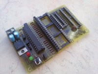
The silk is poor then. C19 and D14 are on opposite sides of U6.
If you leave U6 out, and jumper it's pin 5 to pin 6, you should be good. That will pull D8 of the controller low and start the power up cycle. Then you could leave D13, D14, D15 , C19 and R20 out as well.
If these are boards from Thimios, The orientation for C11 and C12 is backwards on the silkscreen.
Could it be possible for future protection board replace the 4 optimos with relays to make it cheaper?
Earlier boards had mechanical relays. I've gone to solid state relays because they are safer. My speakers are expensive, so protection is my main concern, not the extra $20 for better relay design.
No i look between C19 and d14☺
I start everything by turning main power on in one click,main psu is connected to control board, amplifier turn on, when the inrush relay is activated
The reason is that i do not want any 'Stand by' circuit☺
Also an option, but then you loose the ability to see the reason of protection switching off an amplifier - control board will loos the power as well, right?
The LED would still be flashing the error code with a fault shut down until the main power switch is turned off.
The LED would still be flashing the error code with a fault shut down until the main power switch is turned off.
Ah! OK, I see. Also an option. I've got such a switch at the back panel. But for me it's important to have trigger control, as all the devices are controlled from the sound processor then 🙂
A modular design is sounding more appealing as we go. Being able to select options by connecting other boards would be neat. It would be easy enough to enable/disable options as you did with the tube relay. A low cost remote speaker relay option would be easy to implement for "budget" builds that way as well.
I'm using some inexpensive and very tough automotive relays for mains switching in my latest incarnation. If they work as well as I expect, a control board/power relay module could be a neat option.
USB communication seems to be kicking my a$$ at the moment. On my first attempt I was able to load a bootloader on an Atmega328 and write software on it with a Uno board jumpered to Reset, D1 and D2. I designed another board and added a 6 pin header for a FTDI USB interface cable along with a full Atmega16U2 USB interface. I was able to load the Arduino bootloader on the Atmega328 and write software to it with the FTDI cable. I was also able to load the USB firmware onto the Atmega16U2, but I can't get it to communicate with the Atmega328. The 16U2 seemed to be working. It showed up in the Arduino IDE as a genuine Arduino Uno, but it hung, then failed in programming. I've since tried to rewrite the fuse bits and now the Arduino IDE doesn't recognize it at all.
Now you have to build a <<fuse doctor>>USB communication seems to be kicking my a$$ at the moment. On my first attempt I was able to load a bootloader on an Atmega328 and write software on it with a Uno board jumpered to Reset, D1 and D2. I designed another board and added a 6 pin header for a FTDI USB interface cable along with a full Atmega16U2 USB interface. I was able to load the Arduino bootloader on the Atmega328 and write software to it with the FTDI cable. I was also able to load the USB firmware onto the Atmega16U2, but I can't get it to communicate with the Atmega328. The 16U2 seemed to be working. It showed up in the Arduino IDE as a genuine Arduino Uno, but it hung, then failed in programming. I've since tried to rewrite the fuse bits and now the Arduino IDE doesn't recognize it at all.
Attachments
Last edited:
That looks like something from my satellite tv hacking days! The Atmega16U2 is surface mount. I've got a USBTiny programmer that works well, but have limited skills with AVRDude. I think I managed to erase the fuse bit settings, but I don't think I managed to write the correct bits back on.
What gear do I need to program the atmega328?
I used an Arduino Uno to program mine. Just pull the Atmega328 out of it and plug it int the protection board.
Another way.What gear do I need to program the atmega328?
You can find a dozen of diy AVR programmers on net.
Software for PC is also free,like Pony programmer I.C programmer e.t.c.
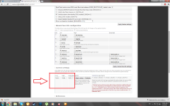
In this case you need the hex file(AVR software.firmware)and fuse settings, you don't need the bootloader.
It is useful if someone can post the right fuse bit settings for this protection board when using Pony programmer.
See picture as reference only!
This may be usefull.http://microcontrollerslab.com/ponyprog-tutorial-beginners/
Attention!!! Wrong fuse settings will make the chip <<death>>
This will be useful again after fuses reset.You need a parallel (H.V) programmer for this,or a <<fuse doctor>>
Attachments

Last edited:
Another way.
You can find a dozen of diy AVR programmers on net.
Software for PC is also free,like Pony programmer I.C programmer e.t.c.
In this case you need the hex file(AVR software.firmware)and fuse settings, you don't need the bootloader.
It is useful if someone can post the right fuse bit settings for this protection board when using Pony programmer.
See picture as reference only!
This may be usefull.PonyProg tutorial for beginners | Microcontrollers Lab
I loaded the firmware with Atmels Flip software through the USB port. Flip doesn't change fuse bits though. AVRDude will set fuse bits if I can figure out the command line language to do it.
I'll check out some of the other software tomorrow and see if I have better luck.
Another issue I ran into was the fuse bit calculators didn't seem to be able to calculate bits for a 16MHz clock on a 16U2. I was using suggested bits I found on the Arduino website.
Do you know this word?
I believe that Valery can help here a lot🙂
I believe that Valery can help here a lot🙂
Attachments
Last edited:
I think those were the values I was trying to program. Maybe I'll have better luck with some more modern software.
- Home
- Amplifiers
- Solid State
- How to build a 21st century protection board